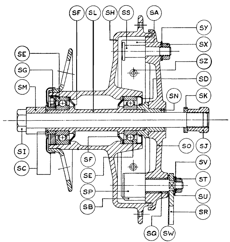
THE FRONT HUB - SECTIONAL VIEW
FIG. 1
| SA | Brake Shoes | SJ | Nut for Detachable Spindle | SR | Lever for Brake Cam |
| SB | Brake Shoe Slipper | SK | Washer for Spindle Nut | SS | Fulcrum Pin |
| SC | Outer Dust Cap and Sleeve | SL | Hollow Spindle | ST | Nut for Cam |
| SD | Inner Dust Cap | SM | Split Sleeve for Spindle | SU | Square Hole Washer for Cam |
| SE | Ballraces | SN | Bearing Clamping Sleeve | SV | Lock Washer |
| SF | Grease Retainers | SO | Brake Plate | SW | Felt Washer for Cam |
| SG | Ballrace Retaining Ring | SP | Brake Cam | SX | Nut for Fulcrum Pin |
| SH | Front Hub Shell | SQ | Bush for Brake Cam | SY | Plain Washer for Fulcrum Pin |
| SI | Detachable Spindle | SZ | Brake Shoe Spring |
THE FRONT HUB, BEARINGS AND BRAKE. (Fig. 1.)
The front hub is supported on a hollow spindle (SL) by two non-adjustable journal ball bearings (SE) which are a parallel-press fit in the hub (SH) and on the spindle. They are packed during initial assembly with high melting point grease which is sufficient for at least 20,000 miles running without attention, in normal circumstances.
Dismantling.
Dismantling the bearings for renewal or for repacking with grease is carried out as follows:
Remove the front wheel assembly from the fork. On removal of the wheel the fork sliders will tend to spring over to the right. They are set in this way intentionally to keep the springs secured in their mountings when the wheel is in place. Pull out the brake plate and brake shoe assembly from the drum. The bearing clamping sleeve (SN) will probably come away with the brake plate. Enter a brass or aluminium punch in the opposite end (left-hand side) of the hollow spindle and drive the spindle and the brake side ball bearing out towards the brake drum. A punch about 9-in. long by just under Z-in. diameter reduced to just under Q-in. diameter for about Q-in. at one end will be needed. (The same punch also suits the rear hub.) The dust caps (SC and SD) from both sides, will be removable now, together with the grease retainer (SF) from the brake side. The left hand ballrace and retaining ring (SG) will remain.
Unscrew the ballrace retaining ring and drive out the bearing (SE) towards the left, using a punch about 9-in. long x 1 3/16-in. diameter, reduced at one end to just under 7/8-in. for about 1/2-in. The other grease retainer (SF) will now be free.
Reassembling Front Hub Bearings.
Place one grease retainer (SF) convex side inwards into the ballrace housing in the left side of the hub and enter the ballrace into position. Press or drive the ballrace home in the housing, applying the pressure to the outer race only. Pack firmly with high melting point grease. Refit and tighten the ballrace retaining ring. Replace the other grease retainer in the brake side ballrace housing, convex side inwards, and pack the housing with grease. Take the hollow spindle with ballrace fitted to it and enter the spindle through the grease retainer and hub, locating the end in the left-hand ballrace, and the brake side ball-race in its housing. Press the spindle and ballrace home. Note that if the brake side ball bearing was removed from the spindle that it is fitted to the shorter ground end of the spindle. Incorrect mounting (on the longer end of the hollow spindle) will make it impossible to assemble the hub correctly.
Pack the bearing with grease and press the inner dust cap (SD) into the hub. On the opposite side, press the outer dust cap and sleeve assembly (SC) on to the protruding end of the hollow spindle.
Refitting the Brake Plate and Shoe Assembly.
Verify the condition of the brake liners and renew them, or fit a pair of re-lined brake shoes, if the liners are worn flush with the rivet heads. See that the cam works freely and ease off if tight. See that the bearing clamping sleeve (SN) is in place in the brake-plate and fit the brake plate and shoe assembly in the drum, locating the sleeve over the protruding end of the hollow spindle. Refit the front wheel, and check fork for freedom of working.


