About The Site
Removal of Cylinder and Piston
The removal of the cylinder head is dealt with in article Decarbonising the Engine and Grinding In Valves.
Remove the cylinder barrel. This will be made easier if the bolts and studs are freed off first. Note that if compression platest are fitted between the cylinder and crankcase they must be kept aside for refitting when rebuilding the engine.
The piston is removable after taking out one circlip and driving out the gudgeon pin. A slot will be found running into the circlip groove at one side of the piston for the purpose of allowing the use of a sharp brad or scriber to prise it out. Use a soft metal punch against the opposite end of the gudgeon pin, have an assistant support the piston against the force of the blows and drive out the gudgeon pin. Help is essential here otherwise there is a risk of bending the connecting rod. The pin is a light driving fit when the piston is cold.
Inspection of Cylinder, Piston and Rings.
Examine the bore for wear or scoring. The original bore diameters are in the article Technical Data All Models . Reboring is generally considered necessary if wear in excess of .008-in. has taken place or the bore is damaged or scored. Cylinders do not wear uniformly, but the maximum wear will be found to have occurred towards the top of the bore at the back. To measure the wear therefore, take an accurate reading of the diameter from front to back just below the ridge left at the top end of the ring travel. This reading may then easily be compared with a measurement taken below the part traversed by the rings which will usually be found almost unworn. Piston rings should be examined for uneven bearing on the cylinder, excessive gap, or side play in the grooves. Any patches of discolouration on the bearing surfaces of the rings indicate that blow-by has been taking place and renewal may be necessary. The ring gaps of course increase with wear and may increase up to 50% before replacement. New piston rings supplied by us are correctly gapped for unworn bores. Clearances are given in Technical Data All Models.
Pistons and rings are obtainable in two oversizes +.020-in. and +.040-in. on diameter. Oversize piston rings cannot be fitted to a worn bore unless the bore is reground to the correct diameter of the replacement rings, in which case an oversize piston would be essential also.
Compression Plates
It will be noted that M.S.S. and Venom models produced from early 1969 onwards will be fitted with the Thruxton type cylinder (M22/18.) The two .062-in. thick plates present at the base of the cylinder must not be removed in efforts to increase the compression ratio. Compression plates .010-in. or .031-in. thick which may also be present are fitted as required when the engine is initially built.
Dismantling the Timing Cover and Timing Gears.
The timing cover is held to the crankcase by ten screws. Remove these and tap the cover gently at the edges with a mallet or soft hammer to free it from the joint face and pull it off. Do not insert wedges between the races.
Remove four bolts (2; 3/16-in., and 2; 1/4-in.) holding the timing gear steady plate to the crankcase and the bottom rocker and intermediate gear spindles, also take off the nut from the end of the camwheel spindle. The second nut on the steady plate holds the cam oil jet and should be left in place. Remove the steady plate.
Undo the magneto armature nut in the centre of the timing unit. After loosening, the nut will tighten and begin to withdraw the timing unit from the armature.
Pull the cam followers off the spindle, being careful to preserve the “Belleville" thrust washer that is fitted between the inlet cam follower and the crankcase. Draw from their respective spindles the camwheel assembly and intermediate gear assembly. The crankshaft pinion and oil-pump worm cannot be drawn off the shaft until the oil pump is out of the way, but the mainshaft nut (left-hand thread) can be removed at this stage. Preserve the timing shaft (tongued) washer which is behind it.
Removal of Oil Pump. (Fig. 17.)
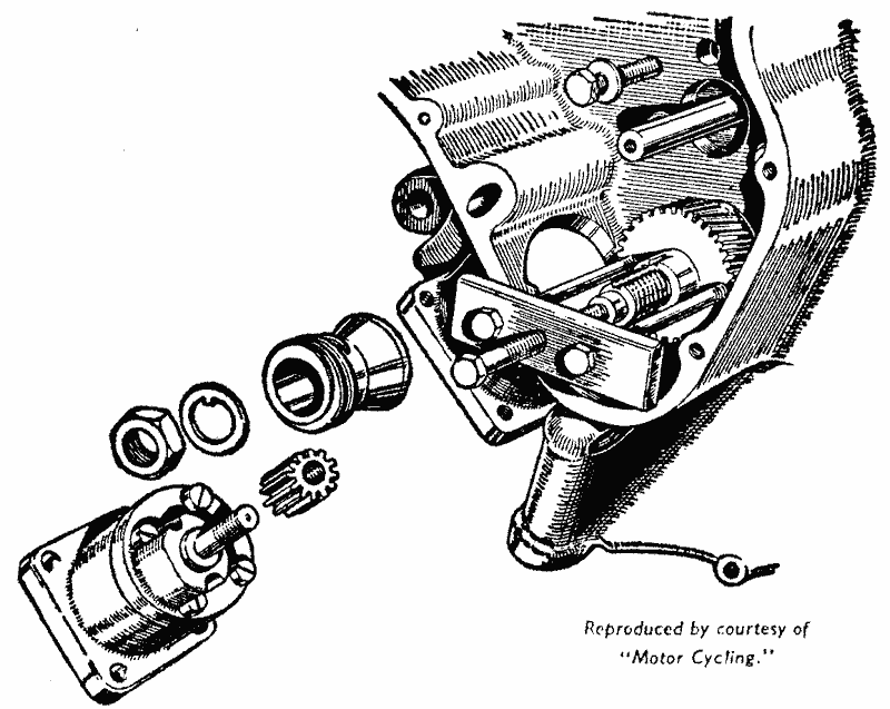
It is important not to attempt to take out the oil pump assembly before heating the crankcase around the pump to expand the pump housing. if forced out cold the housing will be scored which may scrap the crankcase. Take out the four oil pump fixing screws which hold the pump base plate to the crankcase. Three of the holes in the base plate and two of those in the crankcase are visible in the illustration. Note that the screw fitted to the inner front corner is longer than the other three. Heat the crankcase around the oil pump housing. A blow lamp can be used if care is taken not to play the flame continuously on one point or overheat the metal. As the metal is warmed up tap the pump carefully on the top from inside the timing case until it comes clear. Do not tap on the end of the pump spindle. Do not take the oil pump apart unnecessarily. It is seldom that it needs any attention, and if working freely, and if there has been no lubrication trouble it is best left alone, as a special tool is needed to rebuild it.
Dismantling the Oil Pump.
Take out the four screws securing the pump body and its cover to the base plate. Removal of the plate exposes the two return gears and the cover will pull off the pump body bringing with it the pump spindle and the feed gear cut integral with it. The _two return gears and the loose feed gear are then removable from the housing, but as they are taken out mark them with indelible pencil for replacement in the same positions, as it is possible for the two loose gears to be fitted inverted. This is not recommended once the gears have been_working and have bedded in to the respective matching gears on the driving spindle.
Removal Of Oil Pump And Crankshaft Pinion.
The oil-pump Is illustrated after removal and with small driven pinion taken off the crankshaft. Timing pinion is about to be pulled off the shaft with the extractor
Overhauling the Oil Pump.
When inspecting the Pump, scrutinize the recesses in the pump body, in which the gears run, for any signs of scoring on the walls. To work efficiently the pump gears must have the minimum clearance possible between the tops of the teeth and the body. They must also revolve freely with as little end float as possible when the pump body and cover are bolted to the base plate.
End float is removable by lapping down the appropriate end face of the pump body so that when in place the gear end faces are practically flush. Any lapping needed must be most carefully done using medium grade grinding compound and rubbing the pump face whilst held quite flat on a surface plate or sheet of plate glass.
Should new gears be fitted, carefully inspect them for any roughness or fraize around the edges and remove this very carefully indeed by polishing with a strip of superfine emery cloth (Grade OO) held on a small file. To take out the spindle from the Oll pump cover remove the driving gear that meshes with the worm on the mainshaft. Hold the spindle firmly and unscrew the gear anti-clockwise. A convenient method of holding the spindle to avoid damage is to get a scrap splined return oil pump gear, file flats opposite to each other, and hold it in a vice. The splines of the spindle can then be held in the splines in the gear whilst unscrewing the driven gear.
Reassembling the Oil Pump.
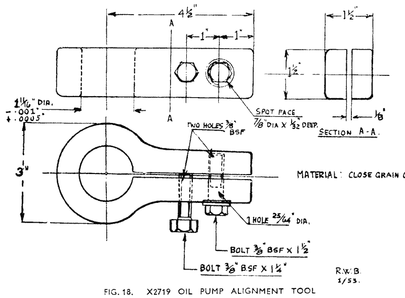
After reassembling the gears and spindle to the pump the pump cover has to be accurately lined up to the body before tightening the four oil pump screws holding the pump to the base plate. For this work Service Tool X2719 oil-pump alignment tool is required (Fig. 18 & 18a).
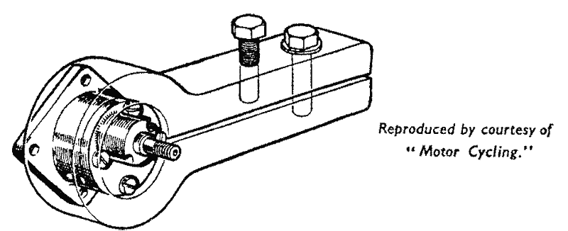
The pump body and cover, loosely mounted to the base plate, are clamped in the tool and the four screws tightened up. Test the pump for freedom of working by turning the spindle. If tight, try slackening off the four screws. If this frees the pump gears the trouble is lack of end play and the pump must be dismantled, the offending gear or gears located, and eased off by lapping down their end faces perfectly square to the bore. Slight roughness or “ lumpiness " can be cured by running a mixture of oil and Turkey stone powder through the pump whilst the pump spindle is rotated in a lathe or drilling machine. After this treatment complete dismantling and scrupulous cleaning in petrol are essential before putting the pump together again in the alignment tool, tightening the body to the base plate and refitting to the engine.
Refitting the Oil Pump to Crankcase.
Heat up the crankcase around the oil pump housing using a blow lamp, but taking care to keep the flame moving about and not concentrated on one spot. Make certain that the crankshaft timing pinion and oil pump drive worm are fitted as they cannot be got into place after fitting the pump. Fit a new base plate gasket over the pump.
Push the pump into the housing lining up the holes in the pump base plate with the screw holes in the crankcase and meshing the driven gear with the worm. The illustration (Fig. 17) shows how the pump is located with the spindle outermost. Tap the pump home and fit the four fixing screws. Note that the long screw fits into the inner front screw hole. This hole is just visible in the illustration in the right-hand bottom corner of the base plate.
Removal of Crankshaft Timing Pinion. (Fig. 19.)
After removal of the oil pump and the left-hand thread mainshaft nut (unscrewed by turning clockwise) pull off the tongue washer behind the nut, and draw the pinion off the shaft, using Service Tool X2721 (Fig. 19). This is_attached to the pinion as shown in Fig. 17 and the tightening of the centre bolt draws the pinion from the mainshaft.
Separating the Crankcase.
Removal of all crankcase bolts and studs enables the crankcase halves to be parted and the flywheel assembly removed. The bearing outer rings will remain in the crankcase and the inner rings with rollers and roller ages come away with the flywheels.
Condition of Main Bearings.
Any uneven wear or pitting of the rollers or roller tracks which would make the bearings run roughly and noisily must be taken as indication that new bearings are necessary. The condition of the outer rings is easily visible without removing them from the crankcase and usually gives some idea of the condition of the inner races, although generally they are less subject to wear than the inners. If the condition of the inner races is in doubt, an inspection can be made after prising out one of the rollers from the cage.
Removal of Main Bearings.
The outer rings are removable from the housings in the crankcase by jarring them out after heating up the housings and the surrounding metal of the crankcase. A blow lamp can be used or the case heated over a gas ring provided that care is taken not to concentrate the flame on one point or overheat the material. A safer method is to immerse the crankcase in boiling water until the housings are expanded to free the bearing rings.
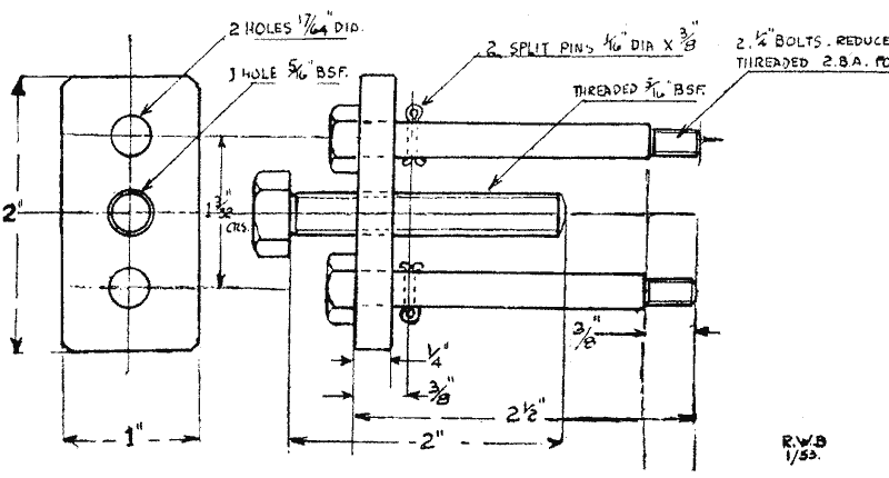
To jar out the rings take the crankcase half, protecting the hands with rag, and bring down the open side smartly and quite square on to the bench top or a large block of wood.
To control the end float on the flywheel assembly the lateral position of the bearing outer rings is set by packing shims inserted during assembly between them and their housing. Retain any shims that are fitted; keeping them so that they can be refitted to the housing from which they were taken. The mainshafts are tapered where the bearings seat. To remove the inner rings, upon which the rollers are retained in cages, the cage must be cut away and the rollers removed. The inner rings must then be split to free them from the shafts. To do this grind through the ring with a small high speed grinding wheel. The operation calls for care and skill as in no circumstances must the grinding wheel be allowed to cut into, or mark the shaft.
Refitting Main Bearings.
Note.- Do not fit bearings before reading paragraph marked *.
The taper roller bearings as supplied each consist of a centre ring, rollers, roller cage and outer ring. The centre ring with rollers and cage will separate from the outer ring, but the components of different bearings must not be interchanged. To fit the outer rings the crankcase must be heated as described above for the dismantling process. When hot place the shims in the housing, or new shims of the same total thickness as those removed, and drop the outer ring squarely into place making sure that the smaller diameter inner end goes in first.
The inner rings each with rollers and cage, are then pressed squarely on to the mainshafts. In this connection be careful not to attempt to fit them on small end first. The taper rollers make it quite clear which way is correct as the larger ends of the rollers must be nearer the flywheel face.
Refitting the Flywheel Assembly.
It is assumed that the big end has not needed attention or has been overhauled as described in this section, and is ready for refitting to the crankcase.
The intermediate gear spindle must be in place in the crankcase and the joint faces should have been carefully cleaned of all old jointing compound. Place the timing side half on the bench resting on the timing case face. Oil the rollers of the timing side bearing and fit the flywheel assembly into position entering the timing shaft through the bearing housing and the rollers into the timing side outer ring. Oil the driving side bearing rollers and fit the driving side half crankcase, setting this in alignment with the timing half. Fit the studs, nuts and bolts and tighten gradually so that the crankcase halves are brought together perfectly square. As the tightening proceeds check the flywheel assembly constantly for freedom of rotation. At the first sign of stiffness in the bearings stop tightening the nuts and bolts and check the extent of the gap left between the joint faces. If the tightening of the nuts, etc., has been done carefully the gap will be the same all round. A gap of .001-in. all round is correct, so that if the shimming behind the bearing outer rings has given this result, the crankcase may be separated for the application of a light smear of jointing compound on the joint faces and may then be reassembled and the studs and bolts finally tightened. Should the crankcase halves meet, leaving the flywheel assembly free to rotate in the bearings extra shimming is needed to take up excess play. First check the amount of end float—if any—and add shims behind the bearing outer rings (which must be removed for the purpose) of the thickness required to take out all float or end play plus .004-in. For example if the flywheel turns freely when the crankcase halves are pulled together tightly with no end play fit one .002-in. shim behind each bearing ring and reassemble. If there is some end play additional shims will be needed - for instance end float of .005 will call for two .002-in. shims on one side and one .005-in on the other.
Overhauling the Flywheel Assembly and Big End.
The tapered shanks of the crankpin fit into correspondingly tapered holes in the flywheel, so that to inspect the big end one shank of the pin must be pressed out of the flywheel.
To separate the flywheels a heavy geared mandrel press or Service Tool X3391 (Fig. 19a) is essential. The flywheel assembly must be placed so that the end of the crankpin is below the ram and the upper flywheel supported so as to allow the shank of the crankpin to be pressed down and out of the flywheel, taking the connecting rod assembly and lower flywheel with it. The connecting rod is then removable leaving the rollers and roller cage on the crankpin which is still fixed in the lower flywheel. Before removal mark the rod for replacement the same way round. If renewal of the big end outer ring is necessary press out the old ring and press in a new one square to the bore and set it centrally with the rod. Also check the fit of the gudgeon pin in the small end bush and if slack refer to replacing the small end bush.
Pull the roller cage and rollers off the crankpin and inspect the roller track for wear and pitting, or breaking up of the hardened surface. Near the edges the pin will be polished, from contact with the cage and provided that any wear here does not leave the roller track unsupported can be disregarded. Such wear will often appear to be much greater than it is. Replacement rollers, which are obtainable .0002-in. or .0004 oversize in diameter, as well as standard, may be used to take up slight play if the outer ring and crankpin are in good condition.
Final assembly of the big end must leave the connecting rod quite free to rotate. Barely perceptible vertical play is permissible without oil in the bearing; there will be about .008-in. in side play. Slight stiffness can be eased by careful lapping of the outer ring when in place in the rod, or by lightly polishing the crankpin.
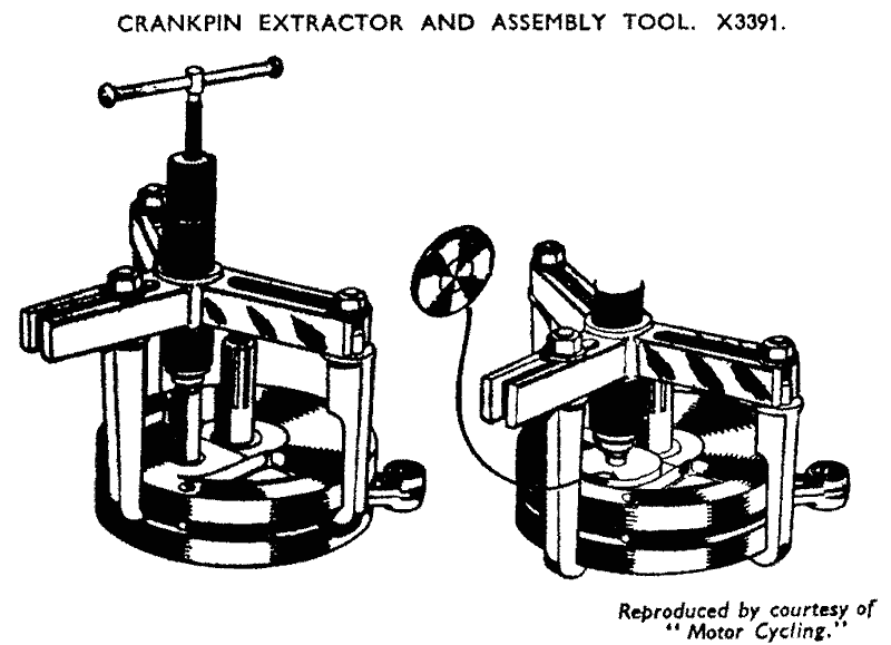
To renew the crankpin the old one must be removed from the flywheel in which it was left when dismantling, by supporting the flywheel on the press and pressing it out.
The crankpin is not drilled, so that it may be fitted either way round. See that the pin is quite clean and wipe out the hole in the flywheel. Push the pin into place and press until nearly flush with the outer face of the flywheel around the crankpin hole. Force oil through the oilways in the timing shaft, fit the roller cage and insert the rollers. These can be held in place with a little grease. Fit the connecting rod over the rollers observing that it fits according to the markings made when dismantling.
Place the other flywheel in position over the crankpin and line up the flywheel rims as closely as possible using a straight edge across the rims checking at several different points round the circumference. Press down the flywheel on to the crankpin right up‘ to the shoulder. As the ends of the pin may protrude a little beyond the surrounding faces of the flywheels, the flywheel underneath should rest upon a stout bush or recessed block. The inner diameter of such a bush or recess must be more than the diameter of the small ends of the crankpin shanks. A diameter of 1.125 is suggested. A block is supplied with X3391.
* In order to mount the flywheel assembly finally for trueing up, some special equipment is needed. If the assembly is to be rotated in its own bearings in V-blocks two “ slave " outer rings should be obtained, or the ones belonging to the engine taken from the crankcase for the purpose. Alternatively obtain two M.87 parallel double row roller races as used in the driving side crankcase on KSS and early MSS models and grind out the inner ring bores taper from 1.0056-in., at the large end to 1.0015-in. - .0005-in. at the small end.
If the taper roller bearings are used whilst trueing, the Y-blocks must be adapted by fitting stops to them to prevent the bearing rings-spreading across the blocks with the weight of the flywheel assembly. The mainshaft must be " clocked " to run true to within .001-in. of complete accuracy. The trueing is done by striking the flywheel rims where necessary with a lead block to correct any inaccuracy left from the initial setting. A heavy lead hammer will be needed to move them.
Replacement of Small End Bush.
Any vertical play on the gudgeon pin in the small end bush calls for replacement of the gudgeon pin or bush, or both. If the pin is worn it is worth trying a new pin in the original bush before deciding to renew the bush . Whilst it is possible to draw out a small end bush and draw a new one into the rod with a suitable bolt and collars, etc., we do not recommend attempting to renew it unless the engine is dismantled and the connecting rod removed. All connecting rods are checked and trued in production after the bushes are fitted and finished to size, ensuring perfect alignment between the small end and big end bearings, and this cannot be assured when other methods of fitting are employed. Further, as the replacement bush has to be drilled in position to match up with the oil hole in the connecting rod there is a serious risk of drillings getting into the crankcase. Connecting rods sent to us for rebushing will be lined up, before return, on a special fixture.
Refitting the Piston and Cylinder.
If the magneto has been removed refit it before fitting the cylinder. It is essential after reassembling the flywheels and crankcase, particularly if a new small end bush has been fitted other than at the factory, to check that the bore of the small end is in line with and parallel to the big end. To test; Obtain an accurately ground mandrel of .8235-in. diameter to fit closely and without play in the small end bush. Set the flywheels so that the lower edges of the small end bush are nearly flush with the cylinder face on the crankcase. Push the mandrel through the bush and check that it lies flat on the face at both sides of the small end. Should it touch at one side, but not on the other, the connecting rod must be reset. The small end eye must also lie centrally in the mouth of the crankcase to avoid side thrust on the piston and this point should be checked, making due allowance for side play on the big end. Fit the piston in place and push the gudgeon pin through the bush finally driving it home up to the circlip, which will have been fitted to the piston. It is a help when fitting if the pin is first pushed into one boss so that it just protrudes inside the piston. The protruding end is then easily entered into the small end bush. Get help to support the piston from the opposite side when tapping the pinhome. Note that the split in the piston skirt must be at the front. Finally fit the second circlip verifying that it seats properly in its groove, and see that the ends do not touch.
New circlips are occasionally found to need a small amount removing from one end to prevent the ends touching, which would prevent proper seating in the circlip groove. Smear the cylinder bore with clean oil, fit a new gasket over the cylinder base. sticking it in place with a little grease, and if any compression plates were fitted originally fit these in place on the crankcase. Set the ring gaps 120° apart. Support the piston and lower the cylinder over it compressing the rings one at a time to enter them in the bore. Lower the cylinder into place and push it firmly into the crankcase. The reassembly of the cylinder head and overhead valve gear is dealt with in the article Decarbonising the Engine and Grinding In Valves
The Timing Gears.
The timing gear bushes in the camwheel and intermediate gear wheel assemblies seldom need replacement, but if renewed must be bored to suit the spindles and not reamed. Boring is essential to ensure the bearing being concentric with the gear teeth. The camwheel bush must be bored to .001-in. above the spindle diameter, and the intermediate gear bush to .0015-in. larger than its spindle. End float on the gears must not exceed .0015-in.
End float must be checked after bolting the steady plate firmly in place. The gears are marked for refitting (Fig. 20). To fit, turn the crankshaft to bring the mark on the crankshaft pinion to the top. Fit the camwheel to its spindle setting the timing mark as illustrated and the cams pointing rearwards. Slide the intermediate gear into place and mesh its teeth with the camwheel and crankshaft pinion so that the marks register. There are two marks on the intermediate gear, but as they are not diametrically opposite the gear can only be fitted in one way to register the marks properly, i.e., with the longer section between the marks facing the front. Note specially that owing to the intermediate gear having one more tooth than the camwheel it changes its position in relation to the other gears and lags behind the camwheel one tooth in every two turns of the crankshaft. The result is that after resetting the timing gears with all marks coinciding, and then turning the crankshaft two complete turns, the marks on the intermediate gear will be out of register with the crankshaft. and cam gears which will be back in their original positions.
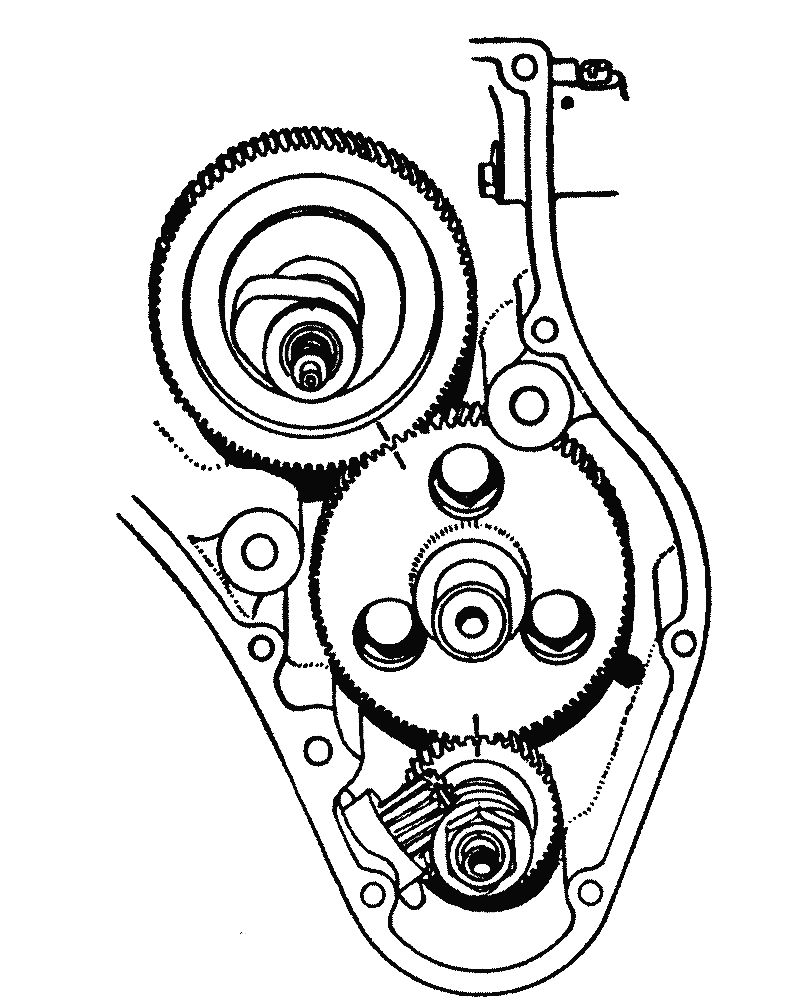
The Intermediate Gear Spindle Bolt Heads are also visible through the holes in the gear. This sometimes leads to the assumption that an engine is incorrectly timed as obviously the chance of the engine stopping so that the marks are in register or even nearly so is exceedingly remote. The marks will all coincide only once every 93 turns of the crankshaft. This feature of the design avoids loading the same teeth at each revolution and evens out any wear that takes place.
The Adjustable Intermediate Gear Spindle.
Mainly for purposes of original assembly the spindle carrying the intermediate gear is made adjustable, so that the backlash between the teeth of the gears may be varied. The adjustment normally does not need any alteration, and the spindle is set when new to give freedom in the gears at all positions with minimum clearances between the teeth. The flange of the spindle is secured to the inner wall of the crankcase by three¼in. B.S.F. bolts which pass through clearance holes in the crankcase thus permitting a certain degree of movement. The flange which is machined with a flat is located by this flat portion fitting against a corresponding flat machined on the crankcase, thus allowing the spindle lateral movement only.
The heads of the spindle holding bolts are accessible through the three holes in the intermediate gear and are shown in Fig. 20, above. Should excess backlash develop between the gears the adjustment can be made by removing the steady plate, slightly slacking off the three bolts and pushing the intermediate gear closer into mesh towards the rear (toward the left of the illustration). It is important not to set the gear too close as this will cause gear wear.
Retiming the Ignition.
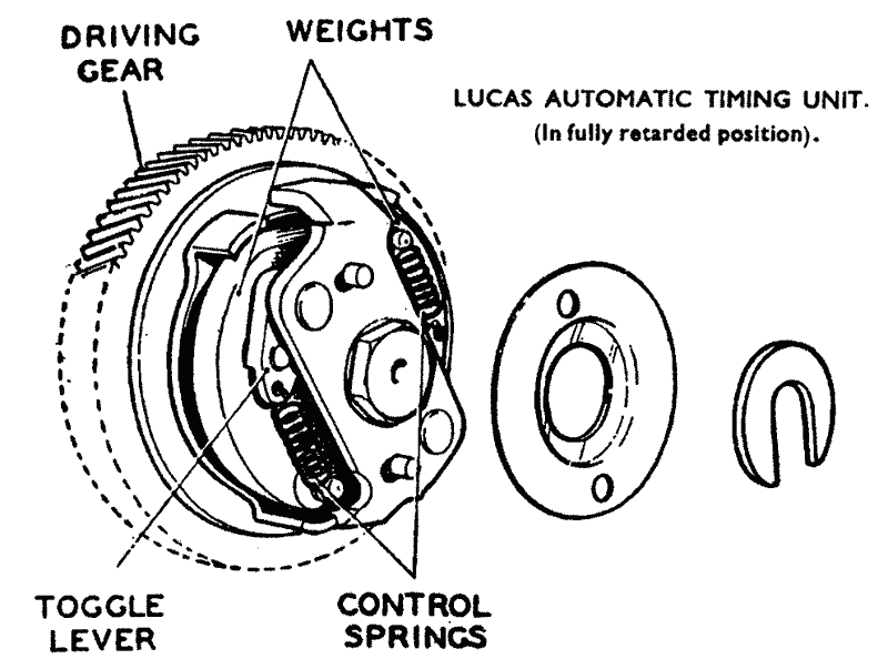
Check and if necessary adjust the contact point gap. Refit the automatic timing unit loosely to the magneto armature. Attach a timing disc to the driving side mainshaft and fix a pointer made of stiff wire to some convenient fixed point, i.e., one of the engine or crankcase bolts. Bring the piston to top dead centre with both valves closed and bend the pointer to indicate zero on the timing disc. Turn the crankshaft backwards 36° as indicated by the pointer. With finger and thumb turn the front plate of the timing unit backwards to its limit, to advance it fully. The plate referred to carries the toggle levers and is shown in Fig. 16. The illustration shows the unit fully retarded. Holding the timing unit fully advanced set the contact breaker points just opening (apart by .0015-in.)
Tighten the centre bolt to fix the timing unit to the taper on the armature. Check the timing before fitting the timing cover as follows :
Turn the crankshaft backwards and see that the contact points close. Open the points with the fingers and place between them a piece of cigarette paper, allowing the points to close on it. Obtain assistance to hold the timing unit fully advanced or insert a small block between the projections of the front plate and the back plate on the gear to wedge them apart. Very slowly move the crankshaft forward maintaining a light pull on the cigarette paper meanwhile. As soon as the paper will withdraw from between the points stop moving the crankshaft and check the position of the timing disc. The reading must be 36° on MSS, 38° on Viper or Venom engines.
Remove the wedge from the timing unit, if one was used, and check the tightness of the timing unit bolt.
Refitting the Timing Gear Cover.
It is advisable always to use a new gasket which can be stuck to the cover with Gasket Goo before fitting. Check that the crankshaft oil feed jet is clear and entered in the bore in the timing side mainshaft. Also engage the holes in the cover over the projecting tip of the cam-wheel spindle and cam oil jet. Tighten the cover screws firmly and evenly. The rocker oil pipe should be left disconnected at the bottom end for the time being so that the oil feed may be checked before finally connecting it and tightening the union (see details in the article Engine Lubrication System).
COIL IGNITION
Engine Timing
Ensure that the 6CA is in the fully advanced position by :-
(i) Removing the cam securing screw. Insert a washer (7/16-in. internal diameter) between the existing washer and the cam.
(ii) Hold the auto advance mechanism in the fully advanced position and re-tightening the securing screw. See diagram in the Venom Thruxton 500 article.
Contact Breaker Timing
(iii) Slacken the two screws which secure the base plate to the engine.
(iv) Turn the engine to the correct timing position, 38° before top dead centre, this being determined, as described above, by the attachment of a timing disc to the driving side mainshaft.
(v) Rotate the base plate until the contacts are just opening. (A low wattage bulb, of appropriate voltage, connected between the contact breaker spring terminal and earth, will be illuminated instantly the contacts separate). Tighten the screws.
(vi) To obtain fine adjustment slacken the two screws (D) securing the C.B. plate and rotate the eccentric cam screw (E), adjusting the position of the C.B. heel until the contacts are just opening. Re-tighten the two securing screws.
Note - On completion of engine timing, remove the 7/16-in. i.d. washer from the auto advance cam securing screw and re-tighten the screw.
Adjusting the Contact Breaker Gap
(i) Turn the engine until the contact breaker gap is open to its widest extent.
(ii) Slacken the screw (B) which secures the angle plate (fixed contact). See diagram in the Venom Thruxton 500 article
(iii) Turn the eccentric cam screw (C) and adjust the contact point gap between the limits 0.014-in. to 0.016-in. (0.35 to 0.40 m.m.).
(iv) Tighten the securing screw (B) and re-check the gap.
For further details see page 110.
See the Venom Thruxton 500 article for wiring diagram.

