About The Site
Description.
The rear suspension is by two self-contained suspension units containing the springs, the damper mechanism, and the oil necessary for damping and lubrication.
The objection to most rear springing systems is that they are unable to cope equally well with both solo and pillion riding conditions. Thus, if the springing is arranged for the heavier load it hardly works at all with a solo rider; and if arranged for solo use tends to bottom when a passenger is carried.
The Velocette rear suspension is easily and quickly adjustable for load in a manner which makes it unique in motor-cycle practice by means of a patented adjustment. Proper working and consequently reasonable comfort are obtainable by a light rider solo, or by two heavy persons, and at all intermediate loadings.
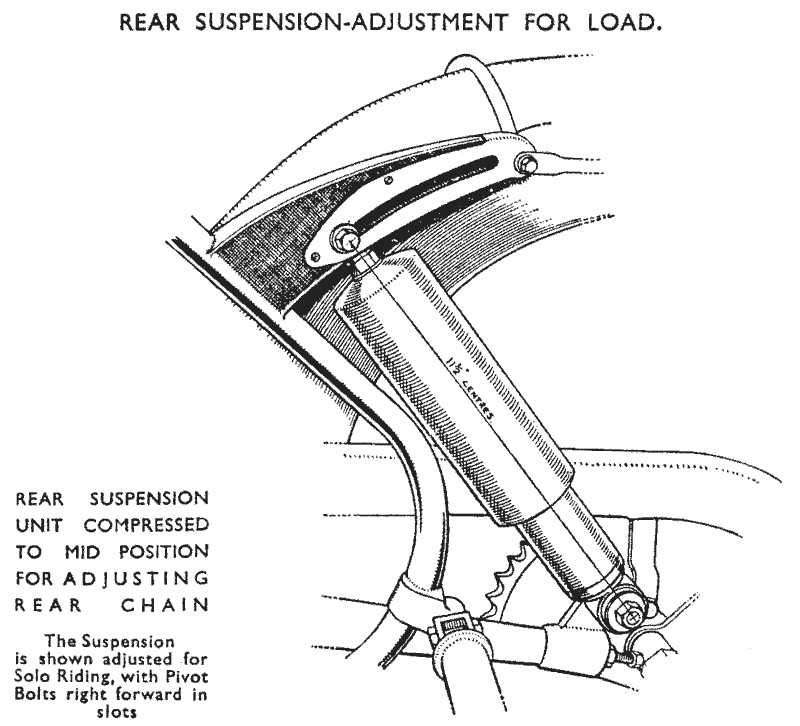
By altering the positions of the top mountings of the spring suspension units along the slots in the support lugs on the frame the springing can be adjusted from “light" - furthest forward as illustrated - to "heavy" - right back. Any intermediate setting can be used, provided that the suspension units are in line, with the upper mounting bolts the same distance along the slots at each side.
Maintenance—Suspension Units.
Apart from external cleaning no attention is necessary. Should it be required to replace the dust covers or springs these are removable after taking the units off the machine. Removal of the covers discloses the springs.
To remove a cover for access to the spring or felt washer first remove the suspension unit from the machine by detaching it at the upper and lower pivots. Hold the unit vertically in a vice gripping the bottom fixing lug between protected vice jaws.
With both hands press down the dust cover against the spring far enough to allow the removal of the two halves of_ the split dust cover retainer. Help will be needed to pull _them out whilst the spring is held compressed (a valve cotter is removed in the same way). The dust cover, washer and spring will then come away over the top lug. The remainder of the unit consisting of the lower part containing the damper mechanism cannot be taken apart, and will be found to function indefinitely.
Rebushing the Suspension Unit Eyes.
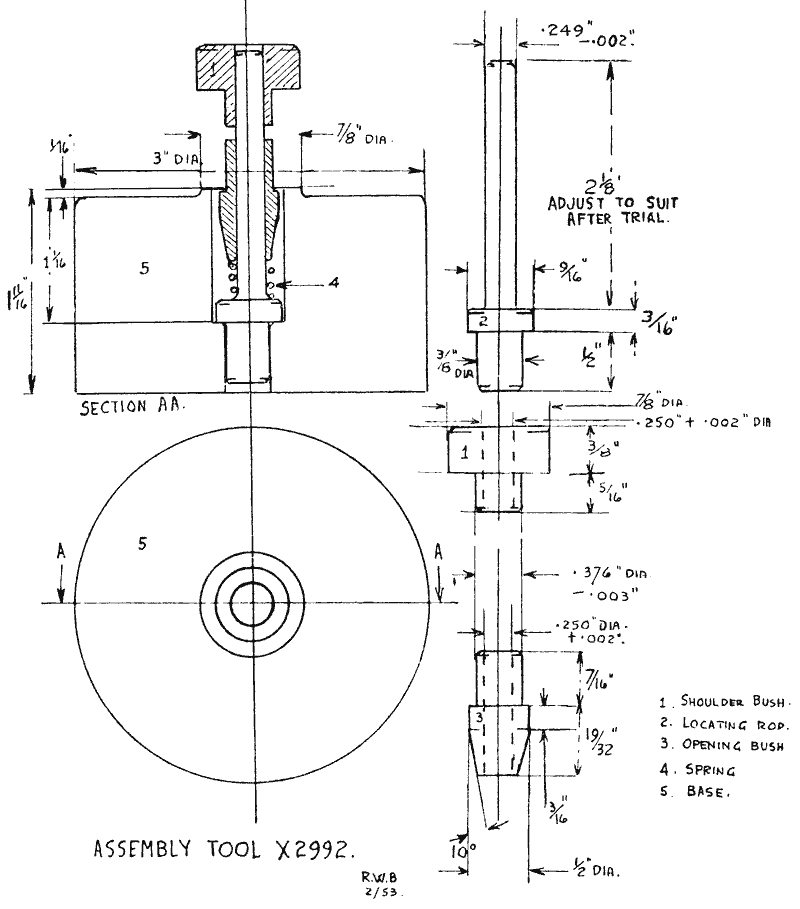
Occasionally the eye bushes may need renewing. Those at the bottom are easily fitted by pushing them into place in the lower eyes, but the top ones call for the use of a special pressing tool—Service Tool No. X2992 (Fig. 25.)
This tool is used by first pressing the rubber sleeve into the eye, resting the fixing lug on the tool with the shoulder bush (I) entered in the sleeve. Before attempting to fit the sleeves lubricate them with soapy water. Remove the shouldered bush (1): Rest the eye, with rubber sleeve fitted, on top of the tool, Fit the distance piece over the Opening Bush

Maintenance--Rear Swinging Fork.
Periodical lubrication of the trunnion shaft bearings through the grease nipples at each side of the trunnion lug on the frame is all that is needed. The greasers are on the underside of the lug. Do not in any circumstances dismantle the swinging fork assembly
needlessly. The torque arm assemblies are very carefully and accurately lined up with each other during assembly at the factory with special equipment, while the clamping bolts are tightened up and the torque tube ends clamped to the trunnion shaft. In the event of accidental damage or if it is essential for the assembly to be taken apart for any other reason the frame with the rear swinging fork assembly should be returned to the factory.
As this may be impractical in the case of Overseas Agents the method of dismantling. and reassembling the trunnion shaft and torque tube assemblies is detailed in the next section.
Dismantling the Trunnion Shaft.
As stated previously the torque arm assemblies should not be loosened or moved on the trunnion shaft, except in case of absolute necessity, such as to enable repairs to be carried out after accidental damage, or to renew the trunnion shaft bushes in the frame.
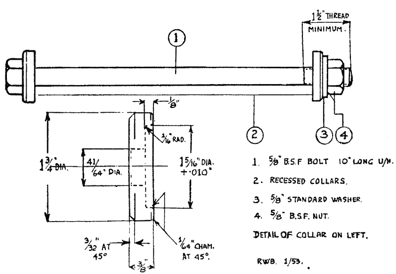
During initial assembly the two torque arm assemblies are lined up using a special torque tube-assembly Alignment Tool No. X2939, which ensures that when the rear wheel is in position the rear wheel spindle is parallel to the trunnion shaft. In addition, a clamp is needed to hold the torque arm assemblies compressed against the trunnion lug felt washer to take up all excess end float. This tool is the Torque Tube Clamp Tool X2938 (Fig. 26)

The trunnion shaft is finished in three diameters, the offside (right-hand) end to take the offside torque arm assembly being .002-in. larger than the centre parallel portion which bears in the trunnion shaft bushes. The nearside (left-hand) end which carries the nearside torque arm assembly is .002-in. smaller than the centre section.
Before attempting to remove the shaft from a Scrambler model see page 95
To dismantle the shaft, therefore, it must be driven out towards the right or offside, after slacking off both trunnion lug clamp bolts and expanding the lugs from the shaft with suitable wedges driven into the slots in the lugs. The lugs must be expanded to avoid scratching the shaft. Care must be taken not to over-expand them and they must be opened only enough to free the shaft.
Before attempting to drive out the trunnion shaft (for which a soft metal spigoted punch is essential) remove the two rubber trunnion shaft end plugs.
After removal of the shaft the felts and felt housings will pull off the shoulders on the frame trunnion lug.
The Trunnion Shaft Bearing.
In the event of worn bushes these _must be driven out of the, trunnion lug, and new ones pressed in, after which they must be accurately bored or reamed out to 1.250-in. +0.00075-in. -0.00025-in.
Reassembling the Trunnion Shaft and Torque Arms.
Fit the trunnion shaft felt Washers and felt housings to the machined shoulders on the trunnion shaft lug on the frame—the housings fit on first, with their flat faces against the lug, and the felts in their recessed faces.
See that the felts are well soaked in oil before fitting, particularly if they are new. Alternatively, soak them for a moment or two in molten tallow.
Set out the torque arm assemblies in the correct positions for replacement, noting that the offside (right-hand) one has an annular groove turned in the bore for identification purposes, and that there is a lug for carrying thg rear chain guard on the upper part of the nearside (left-hand) torque tube.
Hold the right-hand torque arm assembly against the right-hand side of the trunnion lug, and having oiled the trunnion shaft push the smaller end through the torque arm assembly and into the bearings.
As the end comes out at the left-hand side, put the left-hand torque arm assembly (with the lug wedged open slightly) into position and push the trunnion shaft into it. Wedge open the right-hand lug slightly and press the shaft through. When the shaft has been pushed through until the chamfered end just protrudes beyond the face of the lug on the right, the wedges can be removed and the clamp bolts and nuts fitted. Tighten the bolt on the right-hand side fully, but for the time being leave that on the left loose.
The torque arms must now be drawn together towards the frame to compress the felts and to take up the side play. For this the torque tube clamp tool X2938 is required (Fig. 26). Clamp the torque arms to remove all side play, but leave the shaft free to turn in the bushes.
With the torque arms held with the clamping tool fix the Alignment Tool X2939 in position and locate it on the frame lugs with the two pegs. Brlng the torque arms up into line with the holes in the rear ends of the alignment tool and pass the mandrel through the tool and the fork ends. With the torque arms thus held in alignment tighten the left-hand side clamp bolt.
As an alternative, but less satisfactory method of lining up the assembly before tightening the left-hand side clamp bolt, push two well-fitting 3/8-in. bars through the two bolt holes for the rear engine plates. One hole is in the trunnion lug, and the other in the lug at the bottom of the seat tube. A third 1/2-in. diameter mandrel is then placed through the fork ends and the assembly is then raised and a sight taken across this mandrel and the upper one at the front. When the torque arms have been adjusted on the trunnion shaft until the mandrels are seen to be parallel and the clamp bolt lightly tightened, the fork should be lowered and a similar test made by sighting across the bottom mandrel. If there is any variation set the fork by moving one of the torque arms on the trunnion shaft so that a mean between the two “ sights" is obtained.
When correctly aligned tighten the clamp bolt fully and recheck.
It is emphasised that this method of setting the rear wheel spindle parallel to the trunnion shaft is for use only when the proper equipment is not available, and must be considered as a less satisfactory expedient. As its accuracy depends on the fit of the bars or mandrels in the frame and
fork ends respectively and on the bars being perfectly straight it is necessary to get satisfactory materials for the job, and to be most careful when “ sighting ” across the mandrels.


