About The Site
Description of Working. (Fig. 10).
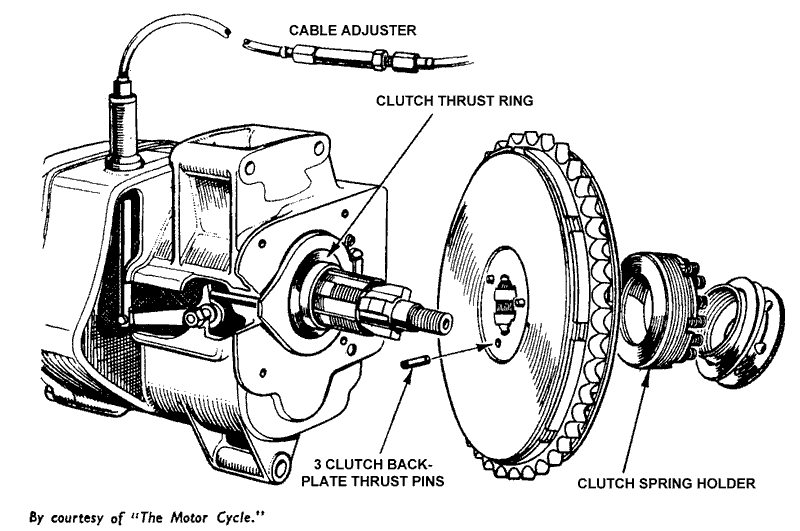
The clutch is operated by a thrust cup carrying a thrust bearing instead of by the more usual single thrust rod operating through a hollow gear shaft as on the L.E. Model, the Valiant, and most other makes. The adjustment which becomes necessary periodically to allow for settling and wear on the friction linings is made by means of the screwed clutch spring holder threaded into the front plate of the clutch, and not by alteration to the cable adjustment. A cable adjuster is fitted, but this is used for controlling the cable adjustment only and must not be used as a “first-aid" remedy for a slipping clutch.
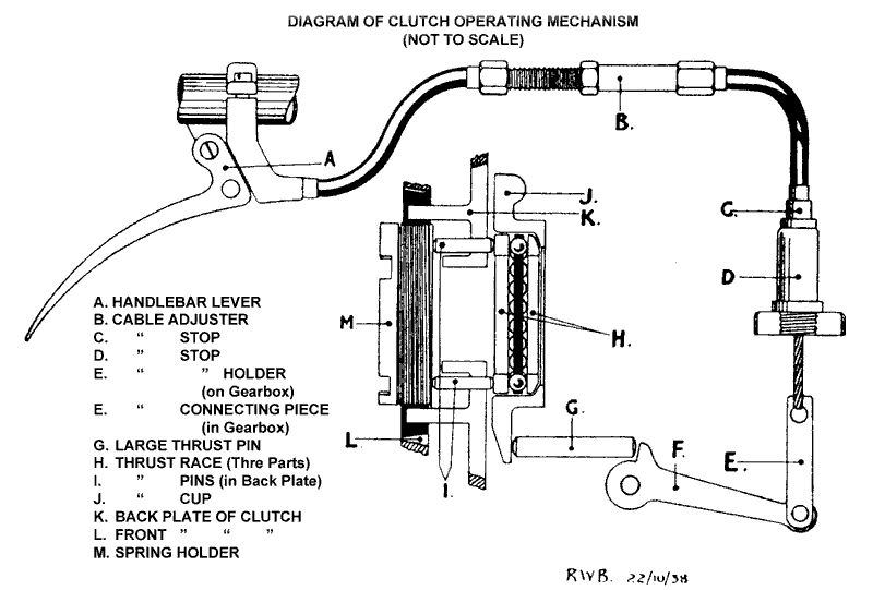
Before attempting any adjustment to the clutch it is important that the operation of the clutch is properly understood and the following explanation should be studied by anyone unfamiliar with the design. The operating mechanism is shown diagrammatically below.

The movement of the handlebar lever (A) raises the operating lever (F) in the gearbox and the raised tip of the lever forces the large thrust pin (G) against the projecting lip of the thrust cup (J), causing the thrust cup to hinge outwards with the opposite side acting as the fulcrum. If the outer clutch plate is observed whilst the handlebar lever is operated, with the clutch stationary, the plate will be seen to tilt outwards, as only that part of the plate nearest the thrust pin side of the clutch is freed from contact with the friction linings.
For the clutch to become fully disengaged the plates have to complete one revolution, after which the spherically seated, self-aligning ball thrust bearing (H) seated in the thrust cup levels the plates and frees them from the friction linings.

The disengagement of the front plate is arranged by the transmission of the outward movement of the thrust through the bearing (H) and three thrust pins (I) against the adjustable clutch spring holder (M) screwed into the front plate (L).
The thrust pins (I) are fitted freely in holes in the back plate (K). Because of the tilting of the front plate the plates are “ peeled off " from contact with each other so that when correctly adjusted and maintained this type of clutch does not cause the unpleasant grating of the gears on starting away which is often noticeable with other makes.
It will be understood that in normal use and a condition of correct adjustment the thrust pins and thrust bearing are free of all thrust loading. It will also be noted that settling or wear of the friction linings will allow the outer plate (L) to close slightly towards the backplate (K) due to the reduction in friction lining thickness. As the thrust cup (I), when not in operation, is held against its seating and the face of the gearbox by a spring clip (not shown), it follows that the initial freedom in the thrust bearing and thrust pins will gradually be reduced, until a stage is reached in which, if adjustment is not carried out the thrust pins and bearings will be carrying part of the pressure of the clutch springs. The result will be clutch slip and premature wearing of the thrust bearing.
In such circumstances adjustment has to be made to the clutch spring holder (M) which must be turned forward (anti-clockwise) in relation to the front plate (L) to restore free movement in the thrust mechanism.
Adjustment of Clutch. (Fig. 11.)
Only in special circumstances, as described later, is adjustment of the clutch cable midway adjuster required.
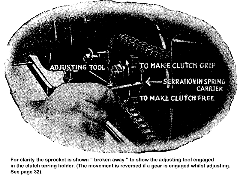
In the ordinary way the adjustment is made by turning the clutch spring holder in the clutch front plate by engaging the flat end of the adjusting tool KA62/2 with one of the notches in the edge of the clutch spring holder through the 1/4-in hole in the final drive sprocket and moving the rear wheel in the direction required.

To use the adjusting peg in the sprocket the front section of the rear chain guard has to be detached from the primary chain case. The chain guard is marked to indicate the need for its removal. The adjustment is made normally with the gears in neutral, and only in an exceptional case is it made when an indirect gear is engaged. Such contingencies will be dealt with later. To prevent clutch slip, i.e., to increase free movement in the operation, pull the rear wheel forward so that the final drive sprocket and adjusting tool will move the clutch spring holder forward in relation to the clutch front plate.
Should the clutch fail to free properly after this adjustment, the clutch cable adjustment may need a little correction : see next section.
Adjustment of Clutch on New Machines or after fitting New Cable Assembly.
The adjustment of the clutch is correct when a new machine is despatched from the factory, but the friction linings (clutch inserts) may settle during the first few hundred miles running, and readjustment may be needed fairly soon.
The clutch cable adjustment seldom needs attention after the initial compression and settling of the outer casings and ferrules of a new cable assembly has taken place. The control cable itself does not stretch, but very slight shortening of the total length of the casings may occur with new parts and has the same effect as a lengthened inner wire. A careful watch should be kept on the clutch lever during the running in period of a new machine, if the clutch has been relined, or a new cable assembly has been fitted.
The settling down of the clutch inserts allows the clutch front plate to close in gradually towards the back plate and reduces the freedom allowed in the thrust bearing during assembly.
This in turn causes the control cable to lose some free movement. On the other hand any shortening of the control cable casings due to compression will tend to hide the fact that the inserts have settled and clutch slip is possible even whilst there is still some lost motion in the cable. It is recommended, therefore, that during the service check normally carried out after the first 500 miles running, the clutch adjustment should be dealt with by carrying out a series of operations, each very simple, exactly as described later and in the order given.
With the clutch in correct adjustment it must be possible to pull back the clutch lever quite freely, and without operating the clutch at all, far enough to move the inner wire (or clutch cable) 1/8-in. to 3/16-in. Should this free movement be seen to have decreased, re-adjustment must be made at once. The sequence of operations for adjusting as mentioned previously is as follows :
Operation 1.—Slacken off the midway cable adjuster fully to allow the nipple to be detached from the handlebar lever and slip it out of the hole in the lever.
Operation 2.—Open both throttle and air controls fully. Select neutral position of the gears, and depress the kickstart against compression and test for clutch slip. If the clutch is felt to slip omit Operation 3 and carry on with Operation 4. If no slip can be felt carry on with Operation 3.
Operation 3.—Using the clutch adjusting peg as already described, pull the rear wheel backward a quarter of a turn at a time checking for clutch slip after each movement. This will involve taking out the adjusting peg from engagement with the clutch spring holder before each test. As soon as the clutch can be felt to slip (and only just slip), proceed with Operation 4.
Operation 4.-- Refit the cable nipple to the handlebar lever. Readjust the midway adjuster until all lost motion is taken out of the cable and the lever is just drawn up against the lever bracket on the handlebar. Do not force the adjustment but only just remove all play. When correct tighten the cable adjuster locknut.
Finally, refit the adjusting peg to the sprocket, engage it with the clutch spring holder, and pull the rear wheel forward a little at a time until free rnovement begins to appear on the cable when the handlebar lever is checked. Adjust until there is free travel on the cable of 1/8-in. to 3/16-in. The adjustment is now completed.
Although the foregoing may seem complicated at first sight the whole “drill " is both easily and quickly carried out, and after the initial settling of a new cable assembly has taken place is only likely to be needed in special circumstances, as for instance if it is not known whether adjustment is needed to the cable or the spring holder. The effect of the two adjustments is inter-related. If in doubt as to whether the cable or spring holder should be adjusted the following should be referred to :
Symptom : Clutch slipping. No lost motion on control cable.
Remedy: Readjust clutch spring holder forward.
Symptom : Clutch slipping. Lost motion present on control cable.
Remedy : Carry out Operation 4 of Adjustment “drill"
Symptom : Clutch not freeing. Normal or excess lost motion on cable.
Remedy : Carry out full Adjustment “drill."
Symptom : Clutch slipping and also not freeing.*
Remedy : Carry out Operation 4 of Adjustment "drill."
* See next section.
It can be accepted that if clutch trouble is not eliminated by carrying out the " drill " exactly as described the clutch will have to be dismantled to attend to a mechanical fault, to rectify incorrect assembly, or to replace worn parts.
Adjusting a Tight Clutch Spring Holder.
If excessive slip through neglect of the adjustment, or a spring holder which is tight in the clutch front plate, causes the clutch front plate to turn with it when adjustment is attempted, the adjustment should be made in the following manner.
Engage either second or third gear, and after passing the adjusting peg through the sprocket, move the clutch by means of the kickstart until one of the notches in the spring holder is opposite the peg and engage the peg in the notch.
To make the clutch grip maize the rear wheel backwards. This is the opposite direction to that used when adjusting with the gears in neutral. By adjusting with an indirect gear engaged advantage is taken of the difference in the rates of movement of the clutch sleeve gear (to which the clutch driven plates are attached) and the final drive sprocket.
Oil in the Clutch.
The primary chain case is intended to carry enough oil to lubricate the chain, and the clutch will grip satisfactorily even if there is an excess of oil in the cover provided that from the outset the cover has had oil in it. It has been found however, that a clutch which has been run completely free of oil over a period will be subject to slip if oil is subsequently introduced on to the friction surfaces. In such circumstances the clutch must be relined, and assembled with oil in the cover.
Dismantling.
If the gearbox has not been removed with the engine from the frame the preliminary work of taking off the dynamo belt cover, belt and primary chain, etc. (see page 31) must be carried out. Unless attention is needed to the sleeve gear ballrace the inner half of the chain case can be left attached to the gearbox.
Draw the clutch assembly off the sleeve gear and push out‘ the three thrust pins from the back plate. With the clutch assembly resting on the back plate lift off the component parts one by one beginning with the front plate. The ballrace is a sliding fit on the centre of the back plate and tight in the chainwheel.
One clutch plate with inserts, and one steel spacing plate fit between the front plate and the chainwheel. Between the chainwheel and the back plate there are two clutch plates and two spacing plates fitted alternately- steel to friction lining.
The inserts will continue to work satisfactorily until worn flush with the metal surrounding them. They must be firm in the plates and chainwheel. The ballrace must be quite free.
Relining the Clutch.
Worn inserts can be pushed out of place and renewed if necessary. Press in new inserts leaving them projecting an equal distance each side and make certain that the working surfaces are all level. Pressing them up against a truly flat surface will ensure this.
Reassembling the Clutch.
The back plate must be held firmly from rotating during re-assembly otherwise the spacing plates cannot be engaged with the front plate. The best thing to hold the plate is a disused sleeve gear from any single cylinder model Velocette. This is gripped in the vice by the gear teeth or driving dogs, and the clutch back plate fitted loosely over the splines. *
Fit the first clutch plate in position followed by a spacing plate, second clutch plate, and the second spacing plate. Note that the external tongues on the clutch plates and internal tongues on the spacing plates must all point away from the chainwheel, i.e., downwards.
Centralize the four plates with the back plate, bring the tongues on each pair of plates into line and engage the internal tongues of the spacing plates in the slots machined in the back plate just inside the ground friction surface.
Hold the chainwheel with the deeper slotted rim underneath and fit it into position with the ballrace over the boss of the back plate. Enter the tongues of the clutch plates in the chainwheel and see that all friction surfaces come into contact. With the chainwheel fitted, put on the third spacing plate and clutch plate in that order and with their tongues pointing upwards, those of the clutch plate being engaged in the slots in the rim of the chainwheel. Centre the spacing plate carefully as its internal tongues must engage in slots on the clutch front plate.
Fit the front plate over the tongues of the back plate and move the chainwheel backwards and forwards maintaining light pressure on the front plate until it is felt to go into place and lie flat on the friction linings as the tongues on the spacing plate enter the slots.
See that the spring holder is screwed into place in the front plate and fit the three thrust pins into the holes in the back plate sticking them in with a little grease.
The clutch assembly is now ready for refitting.
The Clutch Thrust Bearing.
This is a ball thrust bearing seated spherically in the clutch thrust cup and located centrally upon the sleeve gear by a distance-piece pushed over the sleeve gear behind the clutch back plate. There are three parts to the bearing; a hardened steel thrust ring flat on both sides, a cage carrying the bearing balls, and a spherical thrust washer. This has a spherical face to fit the thrust cup and a flat face providing a bearing for the balls during the operation of the clutch. (Fig. 10).
The thrust bearing should be inspected for wear. If pitted the parts affected should be replaced. The plain thrust ring if pitted on one side only often can be reversed to give it a new lease of life. Inspect the distance piece for grooving due to wear and replace if worn. If a new caged ballrace is fitted see that there are no rough edges on the cage that would prevent it sliding freely on the distance-piece. Coat all parts with grease before refitting.
The clutch thrust bearing is not intended to carry a constant thrust load, and when the clutch is correctly adjusted is loaded only when the clutch lever is operated, and the clutch is disengaged. It is therefore important at all times to keep the adjustment correct and when driving to avoid keeping the machine standing in gear with the engine running for longer than is necessary. In circumstances where the engine cannot be stopped, i.e., in traffic blocks, always select neutral.

