When fitting new roller bearings (which are supplied comprising the centre race, rollers, cage, and outer ring) do not mix up the component parts - see that each centre race with rollers is fitted to run with the ring with which it was supplied.
Place one grease retainer in place - concave side outwards or towards the bearing, press the outer ring of the bearing firmly into the recess in the hub until it is hard up against the grease retainer, which it will then hold in position. Fit the two parts to the other side in a similar manner.
To re-assemble a vice is desirable but not essential. First slide the centre of the brake-side roller bearing up to the shoulder on the right-hand end of the spindle. A small collar or washer will be noticed at the shoulder between the ground part of the spindle and the larger un-machined centre part. The inner ring of the bearing bears against this. Slip the spindle into place from the brake drum side and see that the rollers fit into the bearing outer ring in the hub. The' centre part of the bearing must of course be fitted so that the large ends of the taper rollers are outermost. Tap the inner dust cap back into the hub and wipe away any excess grease which may have squeezed out. Put on the flat inside distance washer. Follow up this with the brake plate and shoes, making sure that the small pinion on the reduction gearbox is meshed with the driving gear on the hub. Incidentally, this driving gear is a parallel press fit on to the shoulder of the hub. It is very seldom necessary to replace it, but it can be "prised" out of place using two large spanners packed up (with nuts of suitable thickness) from the back of the brake drum.
Refit the tubular distance piece, spindle-nut and washer, and tighten down the nut to hold the brake plate lightly. Now hold the wheel (brake drum downwards) in a vice by gripping the spindle nut firmly between the jaws. Fit the roller bearing centre into the left-hand bearing ring and tap the inner dust cap into place. Place the flat dust washer in position and tighten down the adjusting nut lightly far enough to allow the wheel to turn freely with only a very slight amount of slackness (about 1/16-in) noticeable at the wheel rim in all positions. Fit the lock nut and screw it down lightly against the adjuster nut. The setting of the bearings is then near enough for the wheel to be re-fitted to the machine. To do this, slack off the spindle nut at the brake side enough to allow the spindle to slide up into the fork end and push the wheel up into place. See that the outside washers are snugly fitted into the recesses in the fork ends, the brake plate engaged with the lug on the fork girder, and tighten down both nuts. Check the adjustment. If incorrect, i.e., wheel tight or excessively slack, see next section.
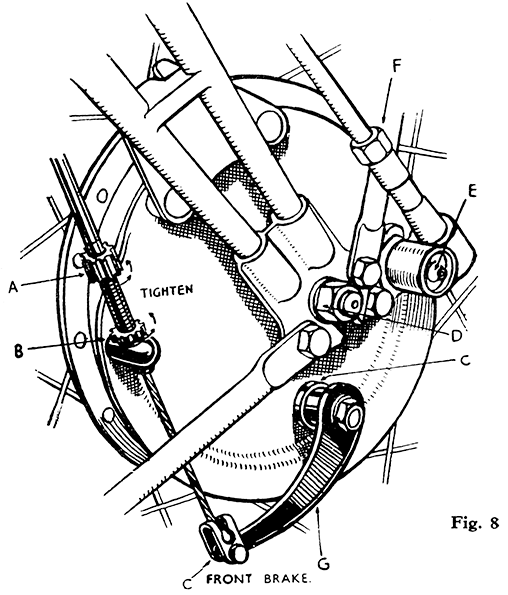
When correctly adjusted connect up the brake cable and adjust the brake (Fig 8).
|
A. |
Adjuster. |
|
B. |
Lock Nut. |
| C. |
Felt Washers (keep oily). |
| D. |
Spindle Nut. |
| E. |
Greaser for Reduction Gearbox. |
| F. |
Nut (securing flexible drive). |
| G. |
Cam Lever. |


