Description and Explanation of Working.
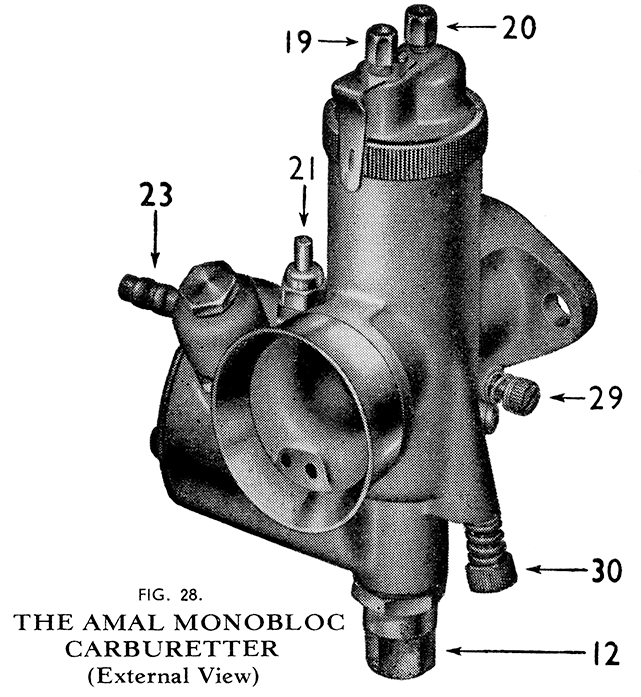
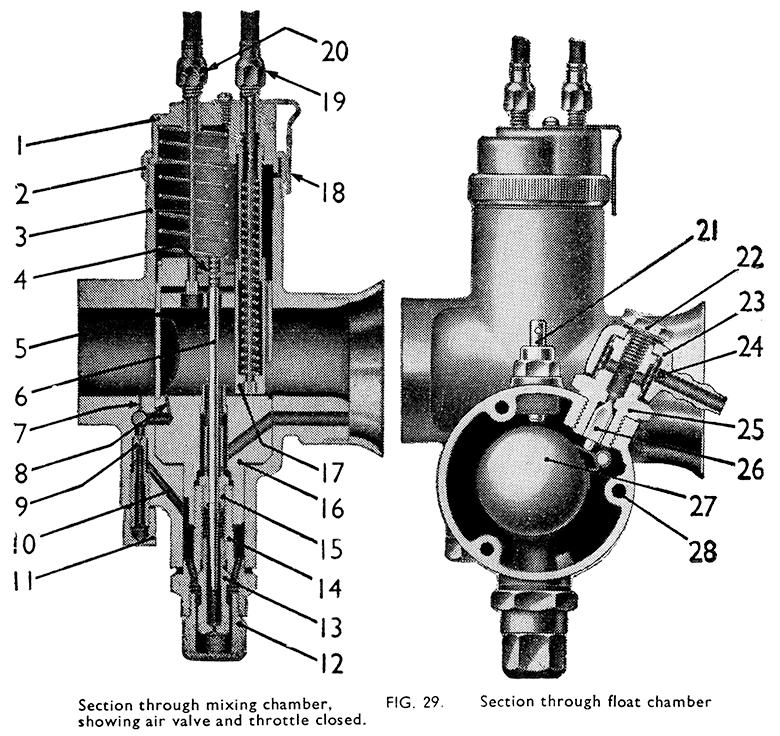
The illustrations should be referred to for explanation of the following sections. The purpose of the carburetter is to atomise the correct amount of fuel with the air that is induced into the engine, and thus supply a correctly-proportioned mixture at all speeds within the engine's range at all throttle settings.
This is achieved by the selection of the correct size main jet, and main choke bore, in conjunction with the right adjustment or setting of the jet needle and the pilot jet.
The volume of mixture, and therefore the power, is controlled from the handlebar twist grip which causes the throttle valve in the carburetter to be raised or lowered and the correct setting of the carburetter provides the right mixture at all positions of the throttle valve.
The opening of the throttle brings into action first the mixture supply from the pilot system for idling at slow speed, through the pilot outlet The further progressive opening of the throttle admits air via the main intake and reduces the depression on the pilot outlet, but in turn a greater depression is created on the pilot by pass causing the mixture to flow from the opening as well as from the pilot outlet. At about 1/8tth of the throttle opening more air is admitted and the mixture is augmented from the main jet the throttle valve cut-away governing the mixture strength from this position of the throttle to about ¼ open. Proceeding up the throttle range the mixture strength is controlled from about ¼ to ¾ open by the position of the needle working within the needle jet. The main jet does not directly spray into the mixing chamber, but discharges through the needle jet into the primary air chamber, and the discharge goes from there as a rich fuel-air mixture through the primary air-choke into the main air-choke. This primary air-choke has a compensating action. After about ¾ throttle opening the main jet is the only regulation. It will be understood from the foregoing that as the main jet only exercises a regulating effect on the mixture strength after the throttle is opened of its travel or over, the fitting of a smaller main jet for economy purposes is useless, and can only cause overheating due to excessively lean mixtures at high speeds. As the mixture strength over the greatest portion of the throttle range is controlled by the setting of the needle within the needle jet, cases of excessive fuel consumption are usually capable of improvement by adjustment of the needle setting (referred to later) or by replacement of the needle jet and for needle because of wear on these components.
A separately operated mixture control is also provided by the air valve, operated from the handlebar, for use when starting from cold, and until the engine is warm enough to accept the full air supply. This air control partially restricts the passage of air through the main choke.
Dismantling the Carburetter.
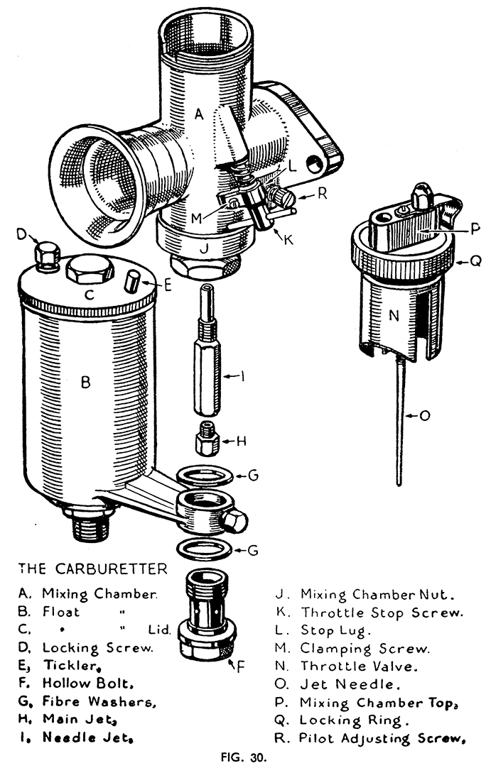
Disconnect the fuel pipe, and unscrew the lock-ring from the mixing chamber. Pull out the throttle and air valves. Remove the carburetter from the engine. Unscrew and take out the float chamber locking bolt, preserving the gaskets from above and below the float chamber banjo. The float chamber is now free for dismantling.
The remainder of the carburetter is dismantled by unscrewing and taking off the mixing changer nut. Retain the gasket inside the nut. The removal of this nut is best achieved by holding it firmly in a vice (with the jaws protected) and unscrewing the mixing chamber off the nut. As the mixing chamber is fairly easily broken by misuse pass a wooden bar carefully through the choke bore and use the bar as a lever to turn the mixing chamber gently and unscrew it.
The jet block will now be capable of being tapped out from the top using a wooden drift to avoid damaging it. It is most important not to use excessive force. Finally screw out the pilot air adjusting screw keeping the small coil spring which is fitted over it.
The Float Chamber Assembly. (Fig. 30).
To remove the float and float needle first loosen the float chamber lid lock screw and unscrew the lid out of the chamber. Compress the spring bow on the float between finger and thumb and press the float needle down through the float and remove it from the bottom of the float chamber.
Should the carburetter have been flooding check the float for leakage by holding it close to the ear and shaking it. The presence of any petrol inside will be easily detected. Petrol can be removed and the lead traced by immersing the float in voiling water to vaporize the petrol which as it comes out in the form of vapour will show up the leak. Whilst it is possible to repair a leaking float by soldering it is not to be recommended except in a case where a replacement float is unobtainable, as it is impossible not to increase the weight of the float by the addition of solder. A replacement should, therefore, by fitted if a float is found to leak or is damaged.
Flooding may also be caused by a bent or damaged float needle or faulty needle seating. If the needle is bent or the seat worn hollow fit a replacement. If the seat is apparently reasonably good push the needle into place, and twist it backward and forward with the finger and tumble whilst holding it upright in the float chamber, and maintainning light pressure on the seating. Do not in any circumstances attempt to grind a needle into the seating.
Before refitting the float chamber lid check the tickler for freedom and make quite certain that the small air vent which is drilled through the edge of the lid is quite clear. Should this hole be obstructed and should the tickler form an airtight seal against the lid (as it often does) this will cause a most baffling fuel shortage, as the engine will repeatedly cut out through the float chamber running dry, but yet the float chamber will at once fill on the tickler being depressed and relieving the air lock.
Reassembling the Carburetter. (Fig. 30).
Make quite certain that all passages in the mixing chamber are clear. It is advisable to blow them out with a jet of compressed air. Also blow through all passages in the jet block and clear the jets.
Enter the jet block into the mixing chamber being careful to set it the right way round so that the dowel at the side enters the slot in the bottom edge of the mixing chamber. Tap it home gently. Fit the gasket to the mixing chamber nut and hold this firmly in a vice. Screw the mixing chamber into the nut and tighten, using a wooden bar passed carefully through the choke bore. Refit the pilot air adjusting screw with its spring and set it 1½ turns open from the fully screwed in position.
Fit the main jet and needle jet, but when tightening remember that these are easily sheared off so that no excessive force must be used.
Refit the float chamber using a gasket at each side of the banjo, and fit the hollow bolt, but do not tighten it fully at this stage.
Enter the throttle and air valves into the mixing chamber. As the throttle valve enters the mixing chamber the jet needle must be centralized and entered into the hole in the jet block and into the needle jet. Fit and tighten the locking ring.
After the carburetter has been fitted to the machine, not forgetting the special heat insulating flange gasket, the fuel pipe may be connected to the tank and the float chamber lined up to meet the bottom union on the pipe. Connect up the bottom union loosely, tighten the hollow bolt whilst holding the float chamber firmly, and finally tighten the fuel pipe union nuts.
Jet and Throttle Valve Markings.
The jet is marked with figures indicating in cubic centimetres the quantity of petrol which it will pass in one minute under a standard pressure. Hence a smaller number indicates a smaller jet.
The throttle valve is marked with two figures at the top, these being separated by a stroke. The first indicates the type of valve, the second the height of the cut-away portion on the atmospheric side of the valve. measured at the centre, in sixteenths of an inch. Hence 6 /3 indicates type 6, with 3/16-in. cut-away, and 6 /4 : Type 6 with 4/16-in., i.e., ¼-in. cutaway.
The valve with the larger cut-away will provide a weaker mixture over that part of the throttle opening range that it controls.
Setting and Adjusting.
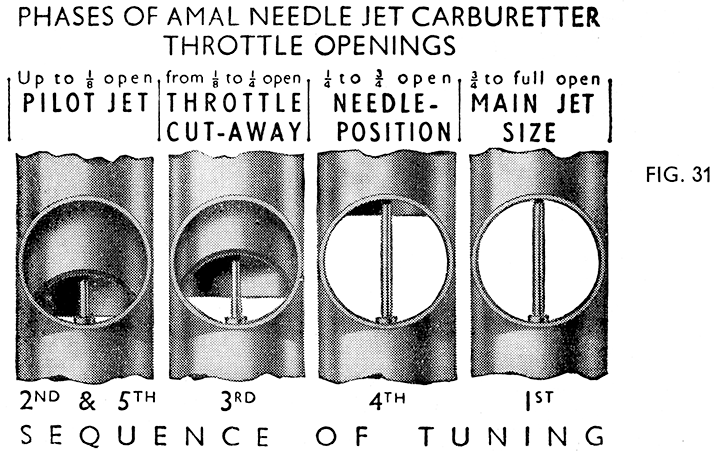
It is inadvisable to experiment with settings differing from that recommended by us, and given on page 6, but the following information is given as being the standard proceedure advocated by Amal Ltd., and should be followed in the order given and studied in conjunction with the illustration (Fig. 31). By adjusting in the correct order any adjustments already set will not be disturbed.
The carburetter is automatic throughout the throttle range and the air valve should be kept full open in all normal running, and need only be closed for starting and until the engine begins to warm up.
1st—Main Jet with Throttle in Position 1.
Test engine for full throttle running. If power seems better with the air valve slightly closed this indicates too small a main jet.
2nd—Pilot Adjustment with Throttle in Positions 2 and 5.
Time will be saved if before making this test the pilot air adjusting screw is first screwed home fully and then set back 1½ turns.
3rd—Throttle Cut-away with Throttle in Position 3.
If, on the throttle being opened with the engine idling, there is objection¬able spitting back from the carburetter, slightly richen the pilot mixture by screwing in the pilot air adjusting screw about a half turn. If this is not effective reset the screw to its original position and fit a throttle valve with the next smaller cut-away.
Should the running be jerky at this throttle opening and there is no spitting back either the throttle needle is set too high, or a larger cut-away is required to cure richness. After long mileage suspect a worn needle jet.
4th—Needle with Throttle in Position 4.
The needle controls a wide range of throttle opening and also the acceleration. Try the needle set as low as possible, i.e., with the clip in an upper groove. If the acceleration is poor and with the air valve partly closed is better, raise the needle two grooves. If very much better try again with the needle lowered one groove and finally leave it where it is best.
If the mixture is too rich with the clip in the top groove, the needle jet and possibly the needle are worn and must be replaced. The needle is found to wear less than the needle jet.
5th - Finally.
Go over the idling again for final touches.
General Hints.
Occasionally the carburetter may flood on turning on the fuel due to the float needle not seating. This can usually be rectified without extensive dismantling as follows : Turn off the fuel. Loosen the float chamber lid lock screw and remove the float chamber lid. Grasp the top of the float needle between finger and thumb and twist it backwards and forwards with a partly rotary movement, at the same time holding it up lightly in contact with the needle seating. After a few twists turn on the fuel again and if no flooding occurs, refit the lid, finally tightening the lock screw.
Excessive fuel consumption may be due to flooding, leakages from carburetter, pipe, or taps. Heavier consumption than normal may be caused by over-rich pilot air setting, particularly if the machine is used a lot in traffic, or by a worn needle jet and /or jet needle.
It is inadvisable to reduce the main jet size as this will almost certainly cause overheating and possibly pre-ignition. Further, the main jet does not control the mixture strength over that range of throttle opening in most frequent use.
Unsatisfactory running may not be due to carburation. If matters cannot be rectified by alterations to mixture strength, and it is known that the feed is regular and sufficient, or the carburetter is not flooding, the cause must be sought elsewhere. Defective or unsuitable sparking plugs or magneto trouble can in some conditions give similar symptoms to faulty carburation.
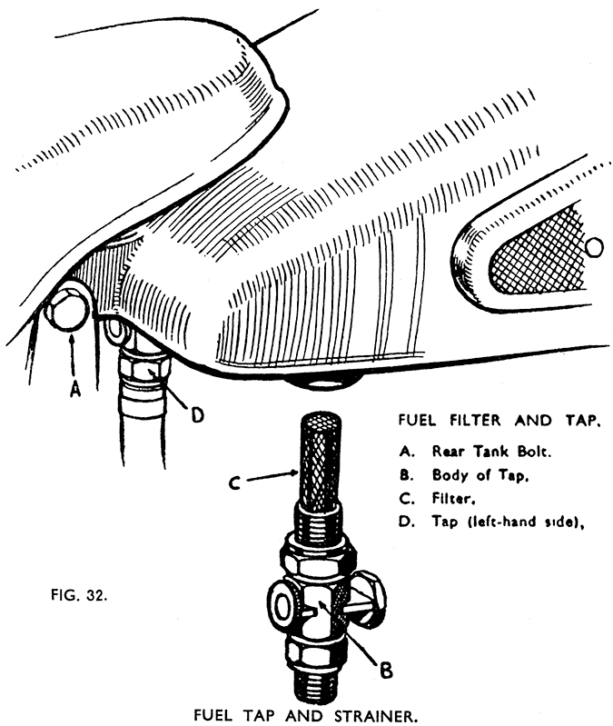
Always keep the fuel filters on the taps clear (Fig. 32) and see that the vent holes in the tank cap, and float chamber lid are clear.


