Removal of Rear Wheel and Brake.
If attention is needed to the brake it is easier to take out the wheel with the brake assembly attached as follows :
Remove the rear detachable section of the mudguard, and the rear chain guard from the left-hand torque tube assembly. Detach the rear brake torque arm, the rear end of the speedometer drive flex from the reduction gearbox, and remove the rear brake adjusting nut. Take out the rear chain connecting link and take off the chain.
Loosen the rear wheel spindle, and the nut on the brake-plate locking bolt on the left-hand side (Fig. 41, page 83). Pull the rear wheel, with brake assembly out rearwards from the fork ends. Complete removal of the nut from the brake plate locking bolt permits the withdrawal of the brake-plate assembly from the drum, and by taking out the wheel spindle and removing the three wheel nuts the drum is freed from the wheel hub.
Relining the Brake.
Replacement brake liners and rivets are available, but it is preferable to fit a pair of replacement relined brake shoe assemblies in exchange for the worn ones. When fitting replacement shoes be careful to fit the steel slippers which protect the ends of the shoes from wear by the cam, and see that the cam works freely in its bearing in the brake plate.
A limited amount of wear may be taken up by inserting thin steel packings between the brake shoe ends and the slippers, but the brake lining rivets must be below the surface of the liner and unable to rub the drum.
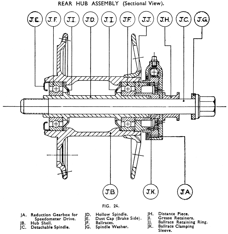
Dismantling the Rear Hub Bearings. (Fig. 24.)
This may be necessary to repack the bearings with grease or to renew them. The barrel of the hub does not carry any grease and the amount needed for adequate lubrication is kept in the bearings by grease retainers fitted between the bearings and the hub.
To dismantle drive out the hollow spindle JD, after pulling off the speedometer reduction gearbox (JA), and the ballrace clamping sleeve (JK). The spindle is driven out from the right-hand side of the machine towards the left and will take with it the left-hand side ballrace (JF) and dust cap (JE). A punch, 9-in. long, slightly less than 7/8-in. diameter, and reduced at one end to just under 5/8-in. for a distance of ½-in will be needed. The same punch is used for dealing with the front hub.
Unscrew and remove the left-hand thread ballrace retaining ring (JJ). The edge of this is slotted in four places. The wider slots will take a bar for undoing the ring. If the ballrace is in good condition and only needs repacking with grease, this can be done without removing it. If renewal is needed drive the bearing out towards the right-hand side using a suitable punch inserted through the hub or insert one end of the hollow spindle into the bearing after removing the left-hand side ballrace, inserting the punch (previously described) into the other end of the hollow spindle.
Reassembling the Rear Hub. (Fig. 24.)
Place the right-hand side grease retainer (JI) in position, hollow (concave) side outwards as illustrated and press the ballrace into its housing. Pack it well with high melting point grease. Fit and tighten the retaining ring (JJ) using a bar across the two wide slots. Press the other ballrace on to the hollow spindle taking care to fit it to the shorter parallel ground end —refer to illustration.
Place the left-hand side grease retainer in the housing hollow (concave) side outwards — pack the housing with grease and fit the hollow spindle through the hub entering the longer parallel ground end in the right-hand side ballrace, and the outer ring of the left-hand side ballrace in the hub. Press the ballrace home. Pack a little more grease into the ballrace and press in the dust cap (JE) hollow side towards the ballrace.
Push the ballrace clamping sleeve (JK) on to the hollow spindle, and fit the reduction gearbox — engaging its driving dogs with the two narrow slots in the ballrace retaining ring. The hub is then ready for refitting.
Reassembling the Brake Plate Assembly.
Push the brake plate support bolt through the brake-drum grease shield.
Fit the brake plate washer in place over the support bolt and fit the brakeplate assembly, at the same time entering the brake shoes in the drum and the end of the support bolt through the hole in the brake cam steady. If desired the hub may now be attached to the brake drum and the wheel with brake assembly fitted to the machine.


