Adjustment.
Slack off the steering damper fully before checking.
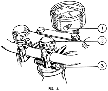
Final adjustment must leave the column quite free without trace of play. To take up play, slack back the top cross member clamp bolt nut (43) and tighten down the column lock-nut (42) until the column begins to bind when checked with the front of the machine supported so that the front tyre clears the ground. Gradually slacken the lock nut until the column is just free, with no trace of play or roughness in working. When correctly adjusted tighten clamp bolt nut.
THE STEERING HEAD
| (1) | Trip Mileage Resetting Knob. |
| (2) | Steering Column Nut. |
| (3) | Clamping Bolt Nut. |
Should the column turn jerkily or roughly suspect that the head race cups and cones are pitted, and dismantle the column from the steering head for inspection and if necessary renew the bearings.
Removal of Steering Column.
This will involve removal of the front fork assembly from the steering head, and is easier if the front wheel is removed first, together with the front mudguard and stays.
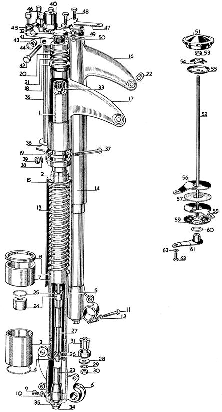
Disconnect the leads from the battery + terminal. Disconnect the speedometer driving flex from the instrument. Unscrew the steering damper knob and rod right out, and remove them. Take off the lower nut from the stud below the steering head lug and remove the ¼-in. B.S.F. bolt (62). Take away the damper plate (58) and friction disc (57) etc. Remove the handlebar clip bolts and caps and lay the handlebar across the tank top after putting a covering of rag or corrugated paper to protect the tank enamel. Replace the handlebar caps and bolts in the positions from which they were taken. The headlamp may be taken right off after removing the front and reflector and disconnecting all wiring from the switch and lamp, or it may be left connected to the wiring and laid back on the tank, after the front fork crossmember (41) Fig. 3, page 13, has been removed.
Unscrew and lift up both fork damper piston rod adaptors (32) and attach to each rod a length of wire, say 22 S.W.G., and about 18-in. long. These wires are essential to pull up the damper piston rods (27) on reassem-bling, and unless secured in this way they will drop down into the fork tubes on removal of the adaptors and will be difficult to retrieve.
Loosen the adaptor lock nuts (33) and screw the adaptors right off the rods. Loosen the clamp bolt nut (43) and remove the column lock nut (40). Support the fork underneath and tap the top cross member (41) up and off the column and fork tubes (1). If the headlamp has not been detached from the wiring, remove it from the brackets (16 and 17) and lay it on the tank. See that it is protected from damage.
Take off the dust cover from the top steering head bearing, and lower the fork gently through the steering head of the frame, meanwhile catching any bearing balls which fall out of the races. The upper bearing cone will be left in the top bearing. Store the fork upright to prevent loss of oil.
Renewal of Steering Head Bearings.
Remove the top cone and all the bearing balls and wipe the parts clean. Inspect them carefully for wear or pitting of the ball tracks. To remove the bearing cups from the steering head lug they must be driven out using a suitable steel punch passed through the head and engaged with the edges of the cups. Work from below to remove the top one and from above for the bottom one.
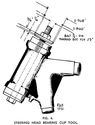
New cups have to be drawn into place quite square with the housings and a convenient way of doing this is to use a ¾-in. bolt 8½-in. long, threaded B.S.F. for about 2½-in., and two stout washers to locate in the cups.
The washers should be not less than 3/16-in. (.1875-in.) thick and must be 1 31/32-in. (1.968-in.) diameter recessed on one edge to 1.860-in. diameter to a depth of about 1/16-in. (.0625-in.) to locate in the cups. (Fig. 4.)
Enter the cups lightly into the housings and with one washer over the bolt, spigot upwards, thread the bolt up through the steering head, fit the other washer, spigot downwards, and thread the nut on to the bolt to hold all parts in place. See that the washers are located in the cups, and the latter quite square, and tighten down the nut until the cups are fully home.
Reassembling the Steering Column.
The bottom steering head cone may be tapped off the column if in need of renewal, and a new one pressed on. Note that the top and bottom cones differ. The top cone is deeper than the bottom one and its inside diameter is smaller.
Stick the bearing balls into the cups with grease, nineteen 1-in. diameter balls in each cup. Push the steering column up into place through the steering head and hold it up firmly into the bearing. Push the top cone down over the column followed by the dust cap. See that the top locating cups (18), the buffers (20), and their housings (21), are all in place on the lamp bracket assemblies. Bring the headlamp forward, leading the wiring down between the lamp bracket tubes and the frame head lug and place the top cross member in position, threading the wires from the damper piston rods through the holes. Fit the column lock nut and screw the adaptors on to the damper piston rods, and tighten the locknuts. Remove the wires and tighten down the adaptors.
Readjust the head bearing as previously described and refit the handle-bar, tightening the clip bolts evenly.
THE FRONT FORK. (Fig. 3.) Description of Working.
Suspension is by coil springs (13), oil damped. The oil for damping. and lubrication is carried in the fork struts.
The working is as follows : On extension of the fork, that is on recoil after a shock, the damper tubes (23) attached to the unsprung sliders move downwards away from the damper piston rods (27) which are fixed at the top to the adaptors (32) on the sprung part of the fork. The damper pistons (26) move into contact with the damper piston rod washers (28) closing the valves. The upward movement of the pistons relative to the damper tubes causes oil from the sliders (5 and 6) to be forced through radial holes in the damper tubes to fill the spaces below the pistons.
On compression of the fork the movement is reversed and the damper tubes move upwards relative to the piston rods, and the pistons lift off the piston rod washers, allowing oil to pass freely from below the pistons through the damper valves (31) into the upper parts of the damper tubes.
Again on recoil the damper tubes below the pistons are replenished, but the oil above the pistons is trapped and can get out only through restricted openings at the top ends of the damper tubes, providing the resistance necessary to give the desired degree of damping
Oil from the upper ends of the damper tubes drains down into the sliders and is available for use again.
The outer lower ends of the damper tubes are shaped to form cones, and any impact sufficient to force the sliders up almost to their limit brings the open ends of the fork tubes (1) over the cones, and a hydraulic lock is formed which prevents metallic contact and " bottoming " in severe conditions.
During the whole time the machine is running over rough surfaces the above cycle of operations is going on, and the more irregular the surface the greater is the degree of damping. It has been found that over almost smooth surfaces the fork works almost undamped and moves freely over slight inequalities in the road, thus overcoming the objection usually found with most damping systems that they prevent movement of the fork altogether under slight impact.
Fitting a sidecar will necessitate heavier springs being fitted to the fork. These are obtainable from us—for details see Spare Parts List.
Maintenance.
Apart from external cleaning, the fork needs no attention. The oil supply lasts almost indefinitely and topping up is unnecessary. Should an owner wish to do so the oil may be drained out and fresh oil put in after 10,000 miles running.
Drain plugs (9) are fitted into the bottom of the sliders at the rear. After refitting the drain plugs, unscrew the two adaptors (32) from the top of the fork tubes. They can then be lifted far enough to get oil in quite
easily. pint (71 c.c.) will be needed in each side.
The Fork Spring Dust Covers. (Fig. 3.)
Occasionally a slight rattle may develop due to a loose dust cover. This must be rectified at once otherwise the rubber washers (15) between the inside of the dust covers and the split sleeves (2) will be damaged and will have to be replaced.
To eliminate rattle the split sleeve on the side needing attention has to be moved up the fork tube to " nip " the buffer. To do this first drain out all oil from both fork sliders. Slightly loosen the clamp bolt (37) on the side required. Do not slack it right off.
Bounce the front wheel sharply several times on the ground until the cover is prevented from rattling and retighten the clamp bolt. The dust covers will never be held so firmly that they cannot be turned by hand, but they must be secure and unable to rattle.
Complete draining of the fork is essential to avoid forming a hydraulic lock which otherwise will prevent the full closure of the fork springs, and the split sleeve will not move. Only partial slackening of the clamp bolt is required as if it is loosened too much the sleeve will move down again when the spring extends.
Refit drain plugs, refill fork with oil, and tighten clamp bolts fully after the work is done.
Dismantling the Fork. (Fig. 3.)
After removal from the machine—described previously—hold the steering column in a vice so that the fork is horizontal. Cover the jaws to prevent damaging the column. The procedure deals with only one strut, but it applies equally to both. Only the sliders (5 and 6) and the lamp bracket assemblies (16 and 17) are handed " and their positions must be noted for correct reassembly.
Pull off the two buffer housings (21) and the locating cup from the top of the lamp bracket assembly. Remove the lamp bracket assembly and the cup (19) in which it is located at the bottom. Slacken off the clamp bolt (37) fully and pull the split sleeve (2) with the main tube, spring, dust cover, and slider, etc., through the bottom cross member of the column assembly away from the column. Twist the assembly when pulling which will make it come away easier.
Remove the column and the other assembly from the vice. Pull off the spring dust cover (14) and the rubber buffer (15) from the split sleeve. Hold the top end of the main tube (1) horizontally in the vice, hold the spring, and tap the split sleeve round until it comes free of the spring. Take the tube out of the vice and remove the split sleeve from it. Hold the slider in the vice and by grasping the spring firmly, twist it out of the mounting on the slider.
Take the slider in one hand and the main tube in the other and after pushing the slider up the tube as far as it will go, draw them apart as sharply as possible to dislodge the oil seal (8) and the slider bush (7) from the top of the slider. The main tube with the fork tube bush (3) will then come away. To remove the fork tube bush first prise the circlip (4) from its groove in the end of the tube and tap the bush carefully off the tube.
The Fork Damper Assembly is removable from the slider after removing the nut (34) and washer (35) from the end of the slider, and will tap out of place. To dismantle remove the damper bush circlip (25) from the damper tube and remove the bush by a similar process to that adopted to remove the slider bush and oil seal from the slider. The damper piston rod (27) with the piston and valve, etc., will then pull out. If the piston (26) or damper valve (31) are removed note the correct order of replacement and see that the shiny face of the piston is set facing the bottom (next to the washer (28). Also when replacing the damper bush (24) note that the end with the chamfer fits uppermost, otherwise the circlip will not go into place.
Reconditioning—A Warning. The slider assemblies will be seriously damaged if stoved at temperatures exceeding 212° Fahrenheit after re-enamelling.
Reassembling the Fork. (Fig. 3.)
Fit the assembled damper to the slider being careful to locate the damper tube spigot properly in the hole in the slider. Fit the washer and nut and tighten. See that the fork tube bush and circlip are properly fitted to the main tube, slide the upper bush (7) over the tube and towards the bottom, noting that the groove across the end face must be facing the bottom bush.
Hold the tube horizontally in the vice and after lubricating the bushes fit the slider over it, entering the damper piston rod through the tube and the bottom bush (on the tube) in the slider. Twist the slider bush (7) to bring the groove, which is cut down the outside, to the top. Hold the slider so that the wheel spindle mounting lug points downwards. Enter the slider bush into the slider and drive it firmly into place using Service Tool Let 796, which consists of a specially shaped split collar which can be fitted over the tube. Remove the tube from the vice and fit the oil seal (8) over it and slide it down to the top of the slider into which it must be fitted by using Service Tool LET 796 once more. Slide the spring down into position and by holding the slider in the vice twist the spring firmly into its mounting. Extend the slider along the tube as far as it will go.
Push the split sleeve (2) down the tube until the upper edge of its taper section is set exactly 7.187-in. (7 3/16-in.) from the top of the tube. Hold it firmly in this position and push the slider and spring towards it, engaging the spring in its mounting on the split sleeve and twisting it firmly into place. Invert the assembly until the damper piston rod protrudes from the tube and attach a piece of wire to it as described on page 12. Fit the rubber buffer (15) and dust cover (14) over the sleeve, thread the wire, and the tube through the bottom cross member, and partly tighten the clamp bolt. See that the assembled tube, spring and slider are fitted on the correct side. The slider which carries the wheel spindle clamp is always on the left (remote from the brake drum).
When assembling the fork—prior to refitting it to the machine—always set the struts so that the fork ends of the sliders point over to the right at about 20° off the centre line. This ensures that when the wheel is fitted after the clamp bolts (37) are tightened the sliders tend to hold the springs firmly into their mountings.
Reassembly of the lamp brackets only calls for care in fitting them to their respective sides and seeing that they are located properly in their top and bottom collars and that the top buffers are fitted between the hollow (concave) sides of the buffer housings.
The wires attached to the damper piston rods enable these to be drawn up for the attachment of the adaptors (32).
Before refilling with oil verify that the dust covers do not rattle, and after fitting the wheel make certain that the fork works freely before finally tightening the spindle clamp bolt. If the dust covers are loose see page 15.
Setting the Front Mudguard Stays.
As a fork is seldom removed and dismantled unless the machine is accidentally damaged, care should be taken when fitting the front mud-guard stays, whether new or repaired ones, that they go into place without having to be forced. Before fitting them therefore they must be set to the correct widths between the ends as follow : Front stay 5 5/16-in. (5.625-in.) ; Central stay, 5¼-in. (5.25-in.) ; Bottom (rear) stay fitted outside the centre stay, 5¾-in. (5.75-in.).
In any instance where the fork does not work freely, and this is not due to the wheel mounting, remove the stays and reset them if needed.


