CHAINS
Maintenance.
The primary chain case will require the addition of oil from time to time and it is usually convenient to squirt a little over the chain from a force- feed oil can whilst the chain is moved forward by the kickstart. The chain cover small inspection cover (Fig. 7) is removed for lubrication purposes.
It is best to remove the rear chain for attention, including thorough washing in paraffin--several changes being used to ensure removal of all dirt.
After draining and drying off, re-lubrication by soaking the chain in molten grease or tallow, preferably containing graphite, is the best method.
The lubricant must be liquid enough to get into the bearings of the chain, but must in no circumstances be boiling. After being satisfied that the lubricant has penetrated the bearings properly, and allowing it to cool off until it begins to solidify, remove the chain and wipe off surplus lubricant.
Adjustment of Primary Chain. (Fig. 15.)
The correct adjustment of the primary chain is ½-in. free up and down movement on one run of the chain midway between the sprockets. In this case the checking is done through the inspection opening in the cover.
The tension must be checked in several different positions so that there is freedom in the tightest place, and the chain must be moved forward by the kickstart and several checks carried out.
Adjustment is by pivoting the gearbox on its bottom-fixing bolt, after freeing off this bolt and the two top ones. To take up excess slack turn the forward one of the two adjusting nuts (Fig. 15) forward on the adjuster and then turn the rear nut in the same direction thus drawing the adjuster, which is attached to the fixing bolt, through the eye-bolt fixed to the engine plate.
When the correct setting is obtained tighten the three fixing bolts and make certain that the adjuster nuts are tight against the eye-bolt.
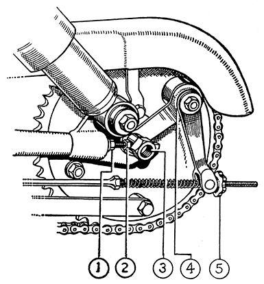
Adjustment of Rear Chain. (Fig. 41.)
The tension of the rear chain is constantly altering when the springing is working, due to the very slight difference between the actual arc of movement of the rear wheel axis from the theoretical arc, that it would traverse if the rear fork was pivoted on the same axis as the final drive sprocket.
 |
| FIG. 41. REAR BRAKE AND REAR CHAIN ADJUSTMENT |
| (1) Chain Adjuster Lock Nut (2) Chain Adjuster (3) Rear Brake Plate Locking Bolt Nut (4) Rear Brake Cam Felt Washer (5) Rear Brake Adjusting Nut |
The variation is slight, but the chain is tightest with the fork in mid-position, that is with the struts compressed to 11½-in. centres, and becomes slacker as the fork swings either up on compression or down on extension of the springs. The adjustment must, therefore, be set to give ½-in. free up and down movement on one run of the chain midway between the sprockets with the struts compressed to the distance as shown (Fig. 24).
 |
| FIG 41a SUSPENSION COMPRESSION STRAP |
To hold the rear springs partly compressed with the swinging fork in the correct position for setting the chain adjustment, a simple strap can be made very easily (Fig. 41a).
Cut off a piece of mild steel strip 12 -in. long, ¾-in. x 1/8-in. material is suitable. Mark off the positions for two holes to be drilled at 11½-in. centres. Drill one hole 3/8-in. dia. and the other 7/16-in. dia.
To use the strap take off one suspension unit, compress the other to enable the strap to fit over the bottom pivot and to be secured at the top by the pivot bolt being pushed through the slots in the frame lugs and the hole in the strap.
As it would be difficult when working alone to hold the struts compressed without a special tool, the adjustment can be made with the fork at its lowest position, but the setting must allow for the chain becoming tighter when the springing is working. If this alternative method is used support the machine on the centre stand, allowing the tyre to clear the floor--this is important.
Now adjust the chain to give 1¼-in. free up and down movement on one run midway between the sprockets.
Whichever method is adopted check the chain in several different positions, turning the rear wheel between checks, to allow the specified freedom in the tightest place.
The alternative method is not so satisfactory as the first one, and if used, the first opportunity should be taken to make a recheck, with the struts held compressed to 11½-in. centres.
 |
| FIG 41b |

