The Electrical System
IMPORTANT NOTE.
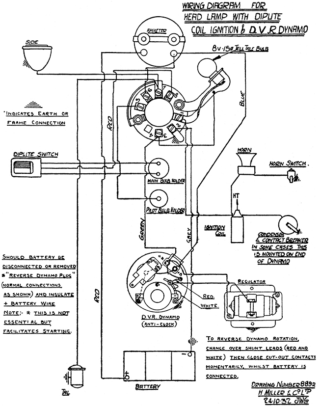
Before making any adjustments to the head lamp or dynamo, disconnect one of the battery terminal connections, otherwise an overheated or burnt-out ammeter may result, or the dynamo polarity may be reversed.
Coil (Miller). Insulated sleeve and terminal cap should be wiped clean with a cloth occasionally. If the coil should be removed be sure to replace it in the underside of the tank with the rubber packing pieces in position.
The condenser is connected to that terminal of the coil to which is also connected the coil to contact breaker cable. If connected to the other coil terminal, the condenser is rendered inoperative and firing will be very erratic.
Contact Breaker (Miller). The lever bearing, pad, rotating cam and contact points are the only wearing parts for this form of ignition. They should be given periodical attention, the lever bearing should be clean and lightly lubricated, the cam smeared lightly with vaseline. The least sign of sluggishness should be remedied by polishing and lubricating the pivot spindle and bearing. The contact points must be free of oil. Great care must be taken to prevent petrol entering the contact breaker when cleaning down—petrol will cause rapid burning of the points—otherwise they may become pitted and dirty, and it will be necessary to file them smooth and flat to ensure perfect contact. They should present a grey frosted appearance. Occasionally put a drop or two of oil on the cam lubricating felt to keep it moist. This will prevent the pad squeaking. When the cam is clear of the pad, the contacts should be pressed firmly together by means of the spring provided. Binding at the pivot bearing will weaken this pressure and prevent the smart make and break so essential for satisfactory results. The points when broken should have a gap of .018" to .020".
WARNING LAMP (Miller).
When fitted, the warning lamp will be found to brighten as the engine slows down, and on stopping, remain full bright if the switch is left on and the contact breaker or timer contacts remain closed.
The warning lamp bulb is connected in parallel with a small resistance and both bulb and resistance are connected in series with the coil circuit when the switch is on. Thus, should the bulb get broken, the ignition will remain unaffected. However, the bulb should be replaced at the earliest opportunity. A replacement bulb will be obtainable almost anywhere, same being a 2.5 volt flash lamp type.
Tests if Trouble is Experienced. The low tension or battery side of the ignition may be checked by turning the ignition switch on and rotating engine slowly. If the ammeter reading fluctuates between zero and 3.5 amps. with the battery up, this part of the system is satisfactory.
On reaching average engine speed, this current value should drop to .75 or .5 amp. If it does not, examine timer contact clearnace and if reduced owing to pad wear adjust to proper clearance. Note : An excess demand by the ignition system will give rise to symptoms which might be diagnosed as a low dynamo output ; therefore check ignition demands with dynamo switch in " off " position.
Too small a gap at the contact breaker points will reduce the charging current shown on the ammeter.
The high tension may be checked by removing the high tension cable and holding the terminal, say, *" to " away from some engine part. Repeat the operation indicated above for low tension test. A spark should be obtainable (when the low tension circuit is broken) if all appears to be in order; examine plug, clean, and if unable to discover the cause of failure, try another plug. If a spark is unobtainable between the high tension terminal and engine body, examine cable and renew if damaged in any way, or if the rubber appears to have deteriorated.
If satisfied that the cable is in order, check condenser, and if this appears to be in order return coil to the makers.
If engine will not fire, or misfires, first see that high tension cable from ignition coil to the sparking plug is not perished or damaged.
On Lucas sets the metal ring on the inside of the contact breaker cover may not be making good contact with the contact breaker housing. If it is dull or dirty give it a rub with fine emery cloth. Also see that hinged spring blade on the contact breaker makes good contact with the condenser case inside the cover.
Should Accumulator Become Damaged so as to be inoperative, a flash lamp battery of approximately four volts if connected to the battery cables will enable a run of approximately 30 minutes to be obtained dependng upon the size of the cells, and again after a short rest a further 20 to 30 minutes.
To Start Engine if Battery is Discharged First ascertain that the sparking plug is clean and the gap between the points does not exceed m /m Remove the earth wire from the accumulator and fasten so that it will not short on the frame. Place the switch in charge position, put the ignition switch in the " on " position. Now run the machine in bottom gear, when it should start. Do not run the engine too fast or switch the lights on when the accumulator is disconnected. Whilst the engine is running the accumulator can be connected up, when it wil commence charging, and the machine can be ridden in the ordinary way.
Should any trouble develop with any part of the electrical system which is not of our manufacture, it should be returned direct to the makers. This will save delay.
For further information dealing with this electrical equipment, see instruction book issued by the makers, which is included with all machines or may be obtained from Messrs. H. Miller & Co., Ltd., Aston Brook Street, Birmingham, or Joseph Lucas Ltd., Great King Street, Birmingham, to whom all queries should be addressed.
Testing Condenser. If the contacts are badly burned, the condenser should be tested, and if faulty replaced. To test condenser, remove it and apply a lighting mains voltage to its terminals—a lamp should be used in series and thus avoid a short circuit in the event of the condenser proving faulty or breaking down during the test. If in order, on removing the mains voltage, an appreciable snappy spark will be obtained on short circuiting the terminals of condenser even after a few seconds pause. If leaky or partially shorted, no spark will be obtainable.
Excess voltage will give rise to burned contact points, but as this condition is only likely to be brought about by running with the battery disconnected, it need hardly be considered.
Ignition Switch. This switch, when off, opens the coil ignition circuit and thus prevents the battery discharging itself when the engine is not required. It is essential that this be used on stopping and starting.
Battery. It is essential to give the battery regular attention, as upon its condition depends the ignition and lighting.
At least once a month remove the vent plugs and examine the acid level. If necessary, add distilled water to bring the level above the tops of the plates, but well short of the bottom of the vent plugs.
If the equipment is laid by for several months, give the battery a small charge from a separate source of electrical energy about once a fortnight, in order to obviate any permanent sulphation of the plates. Do not remove electrolyte from battery and allow plates to dry as certain changes take place which result in loss of capacity.
Complete the inspection by measuring specific gravity of the electrolyte by means of a hydrometer as this gives a good indication of the state of charge of the battery.
Specific gravity figures are : 1.285-1.300 fully charged, 1.210 half discharged, 1.150 fully discharged.
Do not leave battery in discharged condition, and unless some long daytime runs are to be made, remove battery from machine and have it charged from an independent supply.
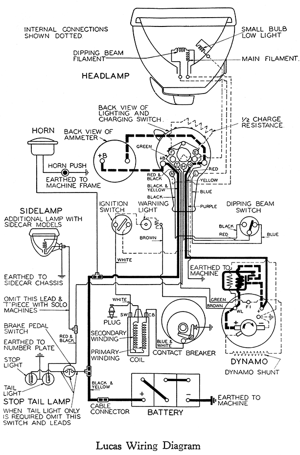
Use of Charging Switch (Lucas). Under normal conditions run with switch in " OFF position. In this position dynamo gives sufficient current for ignition coil. Only use " C ' position for a short time after using lights, or if battery is in low state of charge.
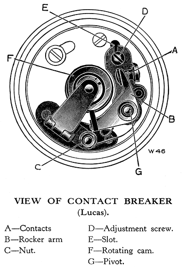
Contact Breaker (Lucas). Occasionally remove cover and examine contact breaker, the contacts " A " must be kept clean and free from oil or grease. If they are burned or blackened, clean with fine emery cloth and afterwards with cloth moistened with petrol. Do not alter contact breaker gap unless it varies considerably from the gauge. To adjust, slacken the locking screw " D " so that the plate carrying the fixed contact can be moved by inserting a screwdriver in the slot E " in the plate. Adjust its position until the gap is set to the thickness of the gauge. Tighten the lock screw after making the adjustment.
When replacing moulded cover make sure that the hinged spring blade on the contact breaker makes contact with the condenser case inside the cover.
Every 5,000 miles place a single drop of oil ou pivot " G " on which contact breaker works, also every 1,000 miles touch the surface of the cam with a match previously dipped in oil. Do not give excess.
Dynamo. The only parts of dynamo needing attention are the brushes and commutator. See that the brushes slide freely in the holders
and " bed " evenly on commutator. Clean dirty brushes with a cloth moistened with petrol. Keep the commutator surface clean and free from oil and brush dust.
Lamps (Lucas). To remove lamp front, press front rim evenly and rotate to the left. The lamp can be focussed by turning bulb in its holder ; by turning bulb in a clockwise direction it is moved inwards, and by turning it in an anti-clockwise direction it is moved outwards.
Replacement Bulbs (Lucas).
| Head lamp (main bulb) | 624 D.V.M.C. |
| Head lamp (pilot light and tail lamp) | B.A.S. 8S |
Ignition Warning Light 252 M.E.S. The burning out of this bulb will not affect the ignition, but it should be replaced as soon as possible.
THE CONSTANT VOLTAGE CONTROL.
IMPORTANT. Battery connections must be maintained clean and tight.
Ammeter indications may vary considerably for the same Dynamo speed (see below).
Do not attempt to adjust regulator, return to makers if considered out of order.
HEADLAMP SWITCH.
Controls lighting only. Charging can take place when the switch is in the " off " position and dynamo is running.
CUT-OUT.
A cut-out is provided to close and open the dynamo to battery circuit. This is automatic and on running up the dynamo, the cut-out contacts will be found to close, and open on stopping.
AMMETER.
Ammeter indications when dynamo is stationary should be zero when switch is in the " off " and " charge " position. With switch in other position and dynamo stationary, the ammeter will indicate discharge due to current flowing through the bulbs.


VOLTAGE REGULATOR.
Dynamo running. Battery up. This is connected directly across the dynamo brushes—it is therefore " dead " whilst dynamo is stationary and cut-out contacts are separated. It operates only when the dynamo is running and the voltage reaches approximately 7.3 volts. Thus a fully charged battery will during day running bring it into operation almost at once and the ammeter charge indicated may not exceed one amp. To those used to the third brush method of dynamo control, this might suggest something to be wrong, but such is not the case. When the battery volts are low due to normal run down conditions, the ammeter charge indications may reach higher values. Day running ammeter indications will therefore be found to vary between one to 6 amps charge,
depending upon the battery conditions.
Night Running. With lamps switched on, the working of the regulator is delayed so that the lamp load plus a charge current will flow before the regulator is brought into action. Here again the charge indicated will depend on the battery conditions. For normal battery and lamp load conditions, a slight charge should be indicated at average road speed conditions, this to ensure stationary and slow running demands on the battery being met satisfactorily.
WARNING.
Dirty Battery Connections also Neglected Discharged Battery Condition will give rise to ammeter indications suggesting fully charged conditions (i.e., low charge rate) and a check for such faulty conditions can be made by switching on the lights—under healthy conditions the light will be bright—otherwise the light will be dull.
All in Order. If after noting the day charging rate, the lights he switched on for a brief period, an increase in this charge rate takes place, it may be safely concluded that all is in order.
No Sign of Charge. Should no charge be indicated, i.e., cut-out contacts fail to close, examine brushes and commutator ; see Miller instruction book page 8. If in order, examine dynamo to regulator cables and connection for earth contact—damaged insulation. If in order, remove regulator cartridge from the clips, run up and if a charge results, carry on temporarily until convenient to fit replacement regulator cartridge. Under these temporary conditions speeds will be found to be higher for the usual charge rate indications so that replacement should be fitted as soon as possible.
Do not atempt to interfere with regulator adjustment. Regulator must be returned to H. Miller & Co., Ltd., Aston Brook Street, Birmingham, either direct or through service agents, who will supply replacements on deposit being paid.

