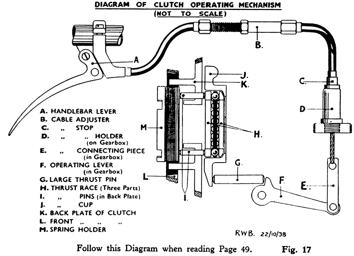
Owing to the unconventional method used for adjusting the clutch, the following explanation should be read carefully in conjunction with Fig. 17. The clutch cable passes through a stop (C) and holder (D) in the top of the gear box, and is attached, inside the gear box housing, to a form of bell crank lever (F) by a connecting piece (E.) The short arm of the bell crank lever bears against a ¼-in. diameter thrust pin (G) which passes through the wall of the gear box housing to emerge behind the clutch back plate, and bear against the clutch thrust cup (J). This cup is hinged to the outer wall of the gear box housing at a point opposite to the thrust pin, so that when the pin is forced out of the gear box by operating the clutch control the thrust cup opens away from the gear box housing like a door, towards the clutch back plate. The thrust bearing (H), which is self-aligning through its spherical contact with the cup, presses the three small diameter thrust pins (I) through the clutch back plate (K) on to the adjustable spring holder (M) which is screwed into the front plate, so forcing the plates to separate.
If the foregoing has been followed carefully, it will be apparent that any adjustment which may be needed is made by screwing the Spring holder further into, or out of, the front Clutch-plate as may be necessary.
In order that there shall be no load on the Thrust-bearing when the Clutch is driving, it is essential that some freedom exists between the thrust-bearing and the Thrust-pins, and this freedom is apparent a the handlebar clutch lever in the form of slack in the outer covering of the clutch Control-cable. There should at all times be slack at this point when the lever is fully released. In other words, the rider should be able to pull back the lever quite freely until the inner cable has pulled out 3/16-in. from the casing before the pressure of the clutch springs is felt. Never allow freedom to decrease below 1/8-in.
After a machine has completed test, the clutch is re-adjusted so that there is the necessary amount of free movement in the clutch thrust bearing, and as the cable adjustment is correct, this free movement is indicated by free movement on the clutch cable at the handle-bar end.
During the first hundred or so miles running with new clutch inserts these tend to "settle down," which permits the back and front Clutch-plates to close together very slightly. This, of course, gradually decreases the amount of freedom in the Thrust-bearing, and is indicated by a gradual reduction in the free movement on the Cable. It is necessary, therefore, to keep a careful watch on the clutch lever, particularly when the machine is new, or after the clutch has been relined, so that as soon as the free movement is reduced to less than approximately 1/8-in., the clutch spring holder should be re-adjusted at once in an anti-clockwise directon to restore the freedom in the operating mechanism. If this adjustment is not made when it becomes necessary, the gradual settling of the inserts allows all the play in the bearing to be taken up and ultimately the thrust cup is forced hard up to the face of the gearbox, and the thrust bearing is subject to a constant thrust load, which it is not designed or intended to carry, the spring pressure on the friction surfaces (inserts) is correspondingly decreased, clutch slip occurs, and damage to the thrust pins and thrust bearing is almost bound to follow. Obviously, therefore, this adjustment (which contrary to the usual practice, is not made by means of the cable adjuster except in special circumstances)is one of considerable importance.


