This control is supplied complete (price 35/-) and can be fitted to any Velocette having a Gearbox incorporating internal Selector and Plunger. It is fitted as standard to the model KTT.
Remove existing hand control lever and rod, also the three top set pins securing the gear box and cover. Exchange kick starter crank for the bent crank provided. Fit on the foot control by means of the three longer set pins provided. To adjust rod for length proceed as follows :—
Move outside striking lever on gearbox (A) till middle gear is engaged (it will then be approximately horizontal). Move gear shift lever of foot control (B) till it is approximately horizontal. This is the middle gear position. It will be found that it is possible to move the end of the lever about 3/8" up and down between two points at which it feels to come solid against the operating pawls. It is now necessary to lengthen or shorten the rod till when connected up, the lever is exactly midway between these two points.
Removing foot lever (C) and cover plate (D) exposes to view the pawls (E). If all is correctly fitted the clearance between the pawls and the ratchet teeth will be equal front and rear.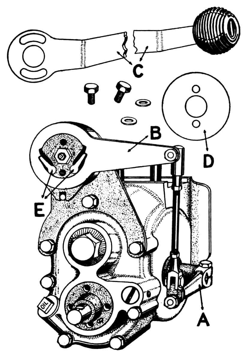
This adjustment is important. The position of the foot lever (C) is adjustable to suit the rider by means of the slots shown.
When all is correctly fitted, force in a good light grease such as Light Castrolease through the nipple with a grease gun till it starts to ooze out. Occasional application of grease gun will keep all internal parts lubricated and exclude. mud and water. Lubricate ball joint and bottom knuckle joint occasionally with oil.
No other attention is necessary. Do not take the device to pieces unnecessarily, particularly do not remove the centralising springs as they are difficult to replace.