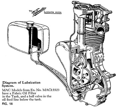
From the oil tank oil feeds by gravity through the gauze filter in the tank and the feed pipe to the oil pump situated in the lower part of the rear of the timing side crankcase. This pump is divided into two distinct parts - the upper pair of gears acting as the feed pump and the lower pair as the return pump. Both sets of gears are fitted in the one pump-body and are driven from the crankshaft by a worm on the main-shaft which meshes with a skew gear on the spindle of the pump. In order that it shall never be possible for more oil to be fed into the engine than the return side of the pump would be capable of clearing from the sump, the return gears are almost double the width of the feed gears. Thus the return side is able to handle nearly double the amount that can be supplied to the engine.
The illustration shows clearly the general arrangement of the lubrication system and should be referred to in conjunction with this explanation.
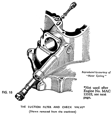
From the feed gears oil is fed out of the top of the pump into the passage drilled in the crankcase that leads obliquely upwards to the face of the timing-chest. On all models up to MAC engine No. MAC 15522 the oil has to pass a ¼-in. diameter steel ball which, when the pump is not working, is held against a seating in the oil passage by a light spring. The spring is held in position by a plug screwed down to a shoulder inside the mouth of the passage. (See Fig. 18). A small steel plate pressed into the oil passage was used instead of the screwed plug up to 1940.
This arrangement is termed the check valve. Its purpose is to prevent any oil flowing into and thus flooding the engine when the machine is left standing. Engines from MAC 15523 have the check valve under the oil tank.
The timing cover which is secured to the face of the timing-chest acts as a distributor for the oil supply. A passage cored in the cover during casting registers with the mouth of the oil-passage in the crankcase and oil is thus fed into the passage in the cover.
By means of the passage in the cover oil is taken to an oil-jet (screwed into the cover) through which a supply passes into the hollow mainshaft and through a drilling to the crankpin, from which it issues from a hole in the centre of the roller track in the big-end. The revolving big-end dissipates the oil over the interior of the crankcase, lubricating the cylinder and piston and small end bearing. This oil ultimately drains to the bottom of the crankcase to be picked up by the return pump.
A second opening in the oil passage in the timing cover is arranged to fit over the end of the spindle carrying the cam-wheel and cams. The oil feeds along the hollow spindle on Engines up to MAC 15522 and passes out through two holes in the spindle to oil holes in the cam-wheel bush and through holes in the cam faces. Lubrication is thus provided directly for the bearing and the cams and cam-followers. From MAC 15523 the working faces of the cams are no longer drilled to provide an oil feed to the cams and followers, and the opening from the oil passage in the timing cover leads only to the cam wheel bush by means of the drilled cam spindle. An extra opening slightly above permits a supply of oil to be fed to the cam oil jet, the outer end of which locates in the cover. Oil from this is directed against the faces of the cams. Engines having this system can be identified by the later type smooth rounded timing cover.
From the upper end of the passage oil is diverted through a drilling in the face of the timing cover into a drilled passage in the crankcase and to the rear of the cylinder wall.
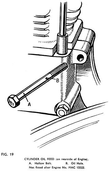
This supply has first to pass through a hollow bolt screwed into the crank case from the nearside. The head of this bolt is marked "jet." A small radial hole in the bolt allows sufficient oil to pass to the oil holes in the cylinder. (See Fig. 19.)
The remainder of the supply is taken by a pipe from the top of the timing cover to the rocker box. The rocker box cover is drilled to lead oil to the large oil grooves in the top bearing surfaces above the rockers.
From the bearings, the oil is free to run away down the push-rod cover into the timing-chest, where it lubricates the timing gears, etc. The crankshaft pinion dips into oil collected in the bottom of the timing-chest. The excess drains through a hole to the sump.(Not on engines after MAC 15522.)
Lubrication of the intermediate-timing-gear bearing is provided from the spindle carrying the gear. The flange of this spindle (inside the crankcase) is drilled to communicate with a groove running the full length of the top of the spindle and a constant supply of oil runs into the oil hole and along the groove from the interior of the engine.
In addition to those parts which are lubricated directly from the pump. the valves and valve-guides receive adequate lubrication.
On engines with separate rocker boxes quite a lot of oil accumulates in the valve spring covers. The supply is restricted to some extent by the provision of two washers, one in each rocker, which are held in place by light springs attached to the tappet covers.
An addition to the system is a fabric filter carried in a cylindrical chamber in the oil tank.
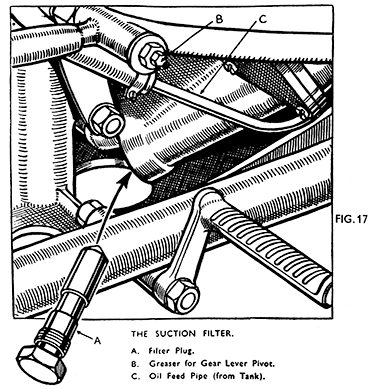
All oil that drains back to the sump is drawn away past a filter plug (Fig. 17) (except on engines prior to M3472, MAC 5079 and MSS 3611) by the return side of the pump which delivers it to the oil tank.
The correct working of the system can be checked by starting the engine and removing the cap from the oil tank. Oil will be noticed returning in an intermittent stream from the top of the pipe just inside the filler neck.
The fact that the return is irregular sometimes give rise to enquiry, but it is quite in order. On starting the engine the return may be almost constant for a few moments due to the amount of oil which has drained to the bottom of the crankcase whilst the engine was stationary, and until this surplus is cleared the return flow will exceed normal. During normal running, however, the return is somewhat intermittent, and mixed with bubbles of air due, partly to the fact that the return side of the pump has practically double the capacity of the feed side, and partly to variations in the amount of oil suspended in the crankcase due to engine speed. For example, upon sudden acceleration the return flow may cease for a time, but will of course resume at a greater rate upon the engine being slowed down.
The Suction Filter. (Fig. 17.)
(Except on engines prior to M3472, MAC 5079 and MSS 3611.)
All oil has to pass this filter before reaching the return pump.
The head of the filter plug is situated at the bottom rear corner of the crankcase on the " off " or right-hand side of the machine, just below the rear engine bolt. It has a right-hand thread.
The body of the plug is machined to fit with a very small diametric clearance from the bore in the crankcase in which it is fitted. The space whilst being ample to pass the oil will not permit anything to pass which could damage or lock the oil pump.
The plug may be unscrewed with the sparking plug spanner and should be removed occasionally for cleaning purposes, usually at intervals of approximately 2,000 miles running. If restricted or choked, excessive smoking at the exhaust will occur due to the return of oil to the tank being prevented, with consequent flooding of the crankcase.
When refitting see that the fibre washer is in place and the plug fully tightened. An air leak at this point will make impossible the proper working of the return side of the system.
The Check Valve
(To Engine MAC15522.) (Fig. 18.)
Occasionally trouble is encountered with excessive smoking from the exhaust on starting, due to oil from the tank draining through into the crankcase when the engine is stationary owing to the check valve failing to close properly. The remedy is to remove the timing cover and reseat the ball. The valve consists of ¼-in. dia. steel ball held on a seating in the main oil passage above the oil pump by a light spring. The spring is held by a plug, screwed into the mouth of the oil passage. It can be unscrewed with a screwdriver and should bring the spring with it. Engines built prior to 1940 have a small plate pressed into the oil-way instead of the screwed plug illustrated. This plate can be pulled out by using a small pair of pliers with narrow jaws.
The passage into which the plug is fitted is readily visible as soon as the timing cover is taken off. The mouth is oval in shape, and its position is well shown in Fig. 40.
As a temporary measure the ball can sometimes be reseated by tapping it lightly against the seat using a suitable punch inserted through the oil feed hole against the ball. As the seat tends to widen under such treatment thus decreasing the unit pressure of the ball upon it the tapping must be carefully done.
As soon as possible the seat should be recut using the special cutter Service Tool No. X2958.
Make sure that the spring is in good order and if necessary renew it:
When re-fitting the check valve plug, screw it down as far as it will go against the shoulder in the oil passage.
After re-fitting the check valve plug and the timing cover, start the engine before attaching the rocker box oil feed pipe to the union on the cover. Oil should be forced out of the union in a steady flow. If satisfactory, stop the engine and connect up the pipe. If no oil comes out see that the check valve spring is not jammed. Slightly ease back the check valve plug and test again.
N.B. - The use of an engine oil of " heavier " grade than recommended, i.e., a Summer Grade during the Winter, may also cause smoking on starting from cold in addition to making starting more difficult, and give rise to symptoms resembling those caused by the check valve leaking.
The Check Valve (from Engine No. MAC 15523.)
The check valve body carrying the 3/8-in. diameter check valve ball and the spring is screwed on to the strainer gauze assembly in the bottom of the oil tank, and the oil feed pipe union nut screws on to its lower end.
To remove the check valve it is necessary first to drain the oil tank. Next unscrew the oil pipe union nut and disconnect the pipe. Unscrew the strainer gauze assembly from the tank.
To take the check valve apart for cleaning hold the check valve body in the vice between aluminium or copper " clamps " to avoid damage to the hexagon, and unscrew the strainer assembly from it, disclosing the ball and spring. The ball, spring and seating may be cleaned and examined.
Should the spring be removed make certain that it is correctly refitted into the ball-valve body and is fully home otherwise the pressure of the spring upon the ball will be too great and will prevent the ball opening when the engine starts. Cases have been known of owners putting back the spring above the ball and effectively cutting off all oil from the engine, so that the above warning should not be disregarded.
After refitting the check valve make certain that the oil feed pipe is full of oil, so that the oil pump is primed, and if the pipe has been removed or the oil in it has run out, pour oil into the open end until the pipe is full and connect it at once to the check valve body.
Refit the tank drain plug, and refill the tank. Start the engine and check the feed (see page 13). If no return is obtained after a few moments running take off the oil pipe once more and prime the pump again.
The Cylinder Oil Feed.
On engines from M3472, MAC5079 and MSS 3611, not after MAC 15522.
Remove bolt below cylinder base joint at rear on left side. Bolt is marked " jet " on head. Clean in petrol. See that small radial hole in the centre of bolt is clear. See that fibre washer below head is in order. Replace. Exercise great care in tightening so that bolt is not sheared off.


