Removal.
Free the rear stand from the mudguard and raise the machine on to the stand. Always choose level ground, but if compelled to work on a slope, have the machine facing uphill, it is then unlikely to run forward off the stand when the wheel is out. Disconnect the rear lamp and detach the mudguard extension. Disconnect the speedometer drive.
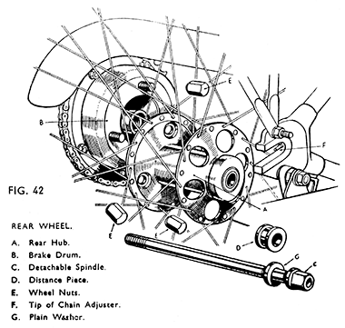
Loosen and take off the three nuts securing the wheel to the brake-drum, unscrew and pull out the spindle from the off-side. As it comes clear of the hub catch the distance piece, which is fitted between the hollow spindle of the hub and the fork-end of the frame. Remove the wheel by lifting it off the studs and pulling it away to the rear.
Replacement.
Lift the wheel into place and fit the three wheel nuts to the studs on the Brake-drum. Place the distance piece in position inside the fork-end of the Frame. See that the plain washer is in place under the head of the Spindle, screw in and tighten the Spindle fully.
Tighten the three wheel nuts fully and refit the mudguard extension.
Connect the speedometer drive flex to the reduction gearbox.
Notes on Above.
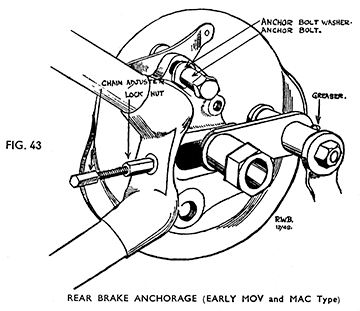
After running about twenty miles after replacing the Rear wheel, check and if necessary tighten the spindle and wheel nuts, in case any bedding down has occurred, On early MOV and MAC Models also check Brake Anchor Bolt for tightness. (See Fig. 43.)
Never lower the machine off the stand on to the wheel unless the Spindle is in position, and on no account remove this spindle unless the weight is taken off the wheel by placing the machine on the stand.
To change a rear Inner-tube it is not necessary to remove the wheel. The old tube can be removed and a new one fitted after removing the Spindle and distance piece.
Removal of Rear Brake.
Take out the Rear Wheel as previously described and on MOV and MAC Models disconnect the Torque-link from the Brake-plate or the Prop-stand Pivot, whichever is the more convenient. Remove chain.
On early MOV and MAC Models the Brake-plate is secured to the frame fork end lug by an anchor bolt which has to be removed to take out the brake-plate. (See Fig. 43).
Loosen the large hexagon nut on the Dummy-spindle and slide the whole assembly out of the fork-end of the frame.
By taking the nut right off the Dummy-spindle the Brake-plate and Brake-shoes will lift right out of the Drum. Be careful not to lose the distance tube which fits on the dummy spindle outside the brake-plate.
BRAKES.
When the adjustment available has all been taken up it is often possible to extend the life of the brake linings by packing the brake shoes from the cam. Suitable packings can be cut comparatively easily from sheet steel and are readily fitted. Cut two strips for each brake. Take off the shoes and fit one packing to each shoe. Before refitting the shoes, see that the rivet heads are well below the surface of the linings. If not - punch them down a little. Should new linings or replacement shoes with new linings be fitted, always smear the surface of the linings with the very slightest film of grease. This reduces the possibility of the drums becoming scored and ridged, and although the efficienty of the brakes will at first be affected, it will rapidly improve and the brakes become perfectly normal.
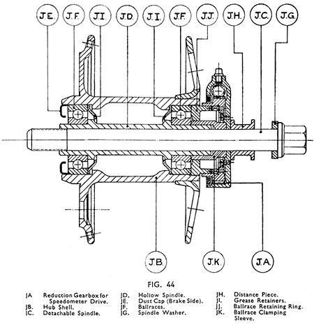
DISMANTLING THE REAR HUB BEARINGS. (Fig. 44.)
Machines supplied new with telescopic front forks have the speedometer reduction gearbox fitted to the rear hub and the ballrace retaining ring (JJ - Fig 44) is left-hand threaded. It unscrews from the hub clockwise. The corresponding part on the previous pattern hub is right hand threaded. Otherwise there is very little difference between the two types and when the reduction gearbox has been taken off the procedure for dismantling and reassembling is the same.
Take out the rear wheel. If a speedometer drive gearbox is fitted draw it off from engagement with the ballrace retaining ring. Remove the clamping sleeve (JK). With a suitable punch inserted into the hollow spindle from the right side of the hub drive it out towards the brake side. (A punch turned from brass or steel is needed and should be about 9-in. long, just under 7/16-in diameter, turned down at one end to just under 5/8-in. for a distance of ½-in.)
The brake side ballrace will come out with the spindle, taking the dust cap (JE) with it. The grease retainer on this side will be freed for removal.
Next unscrew the ballrace retaining ring. The right-hand thread type is dealt with using the pegged end of the spanner A61/2AS. If the later type a steel bar can be passed across the two wider slots in the ring (B) to provide the leverage necessary to unscrew the ring. In this case remember that it unscrews clockwise. Do not damage or burr the edges of the slots or the reduction gearbox will not go back into place. Do not use the narrower slots for unscrewing purposes.
If the purpose of dismantling was to repack the bearings with grease no further stripping is needed as the ballraces can easily be packed and the retaining ring replaced. If the bearings have to be renewed that upon the brake side can be pressed off the hollow spindle and the other one driven out from inside the hub with a suitable punch.
To reassemble the hub first fit the grease retainer into the right-hand bearing housing ; convex side inwards (see Fig. 44) and press the bearing into the housing so that it nips the grease retainer. Fit the retaining ring and tighten fully.
Press the other bearing on to the shorter of the ground ends of the hollow spindle and fit the other grease retainer ; again noting that it fits convex side inwards. Enter the longer parallel ground portion of the hollow spindle into the centre of the ballrace that has already been fitted to the hub and the brake side ballrace into its housing and press home. When fully home fit the dust cap (JE). Fit the clamping sleeve (JK) or if an early type hub is being dealt with press the outer dust cap assembly on to the protruding end of the hollow spindle on the right-hand side. Refit the reduction gearbox engaging the internal driving dogs with the narrow slots in the retaining ring.


