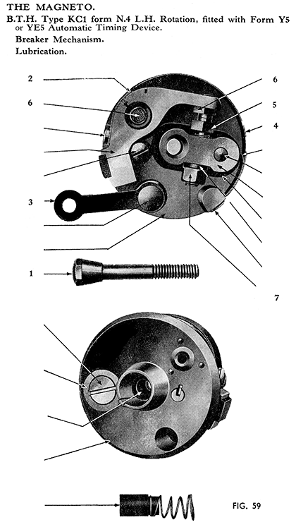
The cam is lubricated by a felt wick in the bottom of the cam ring, which should be given one or two drops of light machine oil. The cam track should also be smeared with oil, but take care to wipe off all surplus oil, leaving only a light oil film on the cam track.
The contact lever bearing is more easily lubricated when the contact breaker is removed for cleaning as described below.
The contact breaker can be removed for cleaning by unscrewing the central hexagon-headed screw (1), and withdrawing the breaker. The contact lever (2) can then be lifted from its bearing bush by first raising and then moving to one side the check spring (3) which is located in the end of the bearing bush.
Care should be taken not to distort in any way the contact lever control spring (4). The points (5 and 6) can be cleaned with a very fine emery cloth, but under no circumstances should they be filed. Wipe away any dirt or metal dust with a petrol moistened cloth.
Before replacing the contact lever smear the bearing bush lightly with thin lubricating oil, wiping off any surplus. Also apply one drop to the wick (6) in the bearing bush.
It is of the Utmost Importance that the Points be kept Absolutely Free from Oil.
Adjustment.
To check the contact setting turn the engine until the contacts are fully opened, and insert the 0.012-in. feeler gauge provided between the contact ; the gauge should be a sliding fit. If there is any appreciable variation from the gauge, slacken the lock nut (7) and turn the contact screw (5) by its hexagon head until the gap is set to the gauge. Finally, tighten the lock nut.
H.T. Cable.
Should be 7 m/m in diameter. Other sizes such as 5 m/m and 9 m/m will not fit in the High-Tension Brush Holder. The cable must be replaced if the rubber insulation has perished or cracked.
Pick-up.
Periodically remove the pick-up or brush holder and wipe it with a cloth moistened with petrol, also see that the carbon brush moves freely in its holder. Before replacing the brush holder, insert the corner of a clean cloth in the aperture in the housing so that it bears against the slip-ring track and the flanges, at the same time turning the engine slowly.
Dismantling.
Total dismantling of the magneto should be rarely necessary, but instructions are given below in case this should be required.
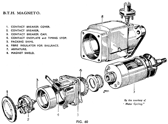
(1). First remove contact breaker cover and contact breaker.
(2). The collector brush holder or pick-up should next be removed before any attempt is made to withdraw the armature from the housing.
(3). The contact end plate can now be removed by unscrewing the fixing screws and the contact breaker cover spring pillar.
(4). The armature can then be withdrawn from the housing.
NOTE.—If the armature is actually withdrawn from the housing it will be necessary to re-magnetise the magnet after replacing the armature; unless a soft iron U shaped and good fitting keeper is placed over the magnet poles before the armature is withdrawn.
Test and Repair.
If the armature has been removed it should be examined for actual structural faults, such as bent or damaged shaft, cracked or broken slip-ring. Special equipment is required to check the winding and condenser and whilst a new condenser can be fitted, in the event of faults of this nature it is desirable to replace with a complete service armature.
Before re-assembling the magneto, carefully examine the bearings, which should be replaced if not in good condition. Special Extractors are required to remove the inner and outer races, and no attempt should be made to remove them by other means. If these extractors are not available, the complete magneto should be returned to the Makers for re-conditioning and a replacement fitted to the machine. When fitting new bearings the following points must be carefully watched :—
(a) The inner race must be square with the shaft, and pressed fully home.
(b) When fitting the inner race at the slip ring end, make sure the washers between the inner race and the slip ring are fitted concentrically, so that the flat washer does not ride on the spindle shoulder.
(c) The outer races are insulated from the housing and contact end¬plate, with serrated fibre washers. It is important that this fibre washer is centrally located before being pressed home.
The bearings should be packed with a suitable High-Melting Point Grease before re-assembly.
Re-assembling.
When re-assembling, the armature should be set up with an end play of 0.002-in. This end play is adjusted by means of shims which are fitted between the magneto body and the contact breaker endplate.
When re-fitting the contact breaker great care should be taken to ensure that the key on the contact breaker base engages with the slot in the armature endplate.
THE AUTOMATIC TIMING UNIT. (B.T.H.)
This unit is now superseded by the B.T.H. unit type YE5. They are interchangeable.
Later type units which do not have the limiting stop peg in the gear do not require the use of a sprag when being removed - see page 57.
The device is incorporated with the magneto driving gear and does not require any attention or adjustment.
Should it be necessary to remove the magneto, the automatic timing device can be removed by undoing the self-extracting nut on the end of the magneto spindle. (Before removal refer to pages 57 and 58). After the nut loosens, it will almost immediately tighten again, and it is then that it commences to withdraw the gear and timing device from the tapered magneto spindle.
Should for any reason the gearwheel be damaged it will be necessary to replace the A.T.D. plate, gearwheel and bearing sleeve assembly complete. To effect this replacement the following procedure must be carried out
To Dismantle the A.T.D.
Remove control spring, being careful not to distort the spring in any way.
Remove circlip.
NOTE.--Special pliers will be required for this operation.
The hub and front plate assembly can now be withdrawn from the gearwheel assembly ; also the five roller weights.
To Re-assemble the A.T.D.
Before commencing assembly, smear all surfaces with light machine oil.
Place the five roller weights in position.
Fit the hub and front plate assembly so that the hole in the hub-for anchoring the control spring is in the correct relationship with respect to the anchor pin.
Fit circlip, making sure that there are no burrs on the face that rubs against the bearing sleeve. See that the circlip locates correctly in the groove in the hub.
With the circlip fitted, the following conditions must be checked
(a) Endplay of sleeve on hub must be between 0.008-in. and 0.002-in,
(b) Total clearance between any roller and the front plate must be between 0.012-in, and 0.004-in.
Fit control spring so that the looped end has to be wound up approximately 450 before fitting round anchor pin.
Finally check advance movement of the A.T.D., making sure that the control spring returns the front plate to the closed position when holding the gearwheel. The movement must be smooth in action
LUCAS TYPE KIF AND AUTOMATIC TIMING UNIT.
Routine Maintenance.
Lubrication. Every 3,000 miles remove the contact breaker and after pushing aside the rocker arm retaining spring prise the rocker arm off its bearing and lightly smear the bearing with clean engine oil. At the same time take out the felt pad from the pocket in the contact breaker housing and soak it in thin machine oil (SAE 10). Remove any surplus oil and refit. (This felt lubricates the cam surface via a hole in the cam.) DO NOT ALLOW ANY OIL TO REACH THE CONTACTS. If any gets on them accidentally clean off thoroughly with a clean petrol soaked rag.
Adjustment.
At 3,000 miles check the contact point gap and if necessary reset to .012" clearance at maximum opening. Adjustment is made by slacking off the lock-nut on the adjustable point, and turning the hexagon head of the point screw in the direction required. Tighten the lock-nut after adjustment and recheck the clearance in case it has been altered in tightening.
Cleaning.
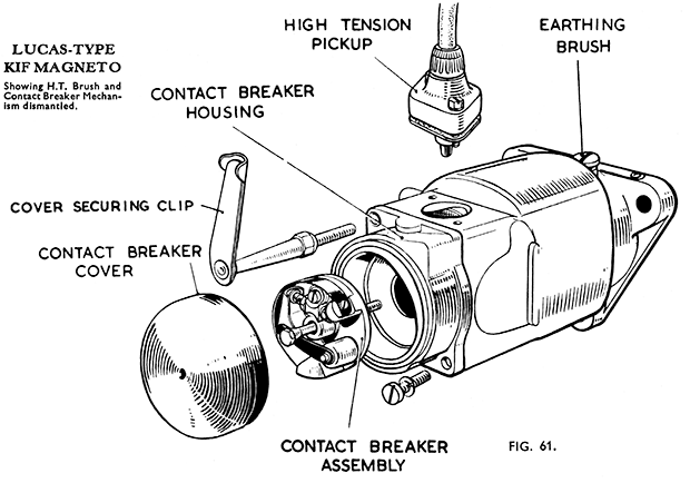
Every 6,000 miles examine the contact breaker points and if burned or blackened clean them with a fine carborundum stone or super-fine emery cloth. Cleaning is easier if the contact breaker is removed first. It is held to the armature by a central pin (see Fig. 61).
Remove the high tension pick-up--held to the magneto by two screws and wipe the moulding clean and polish with a fine dry cloth. Check the pick-up brush for freedom - it must work easily in the holder. Clean the magneto slip ring against which the brush bears and the inner flanges by holding a soft cloth against the slip ring and flanges by means of a suitably tapered piece of wood; whilst the engine is rotated slowly. If the brush is worn to with 1/8" of the shoulder it must be renewed.
Replacement of High Tension Cable.
If the cable shows signs of deterioration through perishing or cracking of the insulation it must be replaced by a suitable length of 7 mm. rubber-covered cable. To renew bare the wire at one end by removing the insulation for about ¼" and thread the moulded nut over the cable. Thread the bare wire through the washer removed from the old cable and bend back the strands over the washer. Screw the moulded nut back firmly holding the cable in place.
Servicing.
(a) Testing Magneto in position on engine to locate cause of misfiring or ignition failure.
(i) Disconnect the suppressor from the sparking plug. Take the suppressor off the cable and hold the cable by the insulation so that the bare wire is about 1/8-in. from some part of the cylinder whilst the crankshaft is rotated smartly by means of the kickstarter.
(ii) If the spark that jumps from the wire is strong and regular, the fault is in the sparking plug. Remove the plug for examination, cleaning, adjustment, or renewal.
(iii) Next examine the high tension cable for security of fixing to the pick-up and check the insulation for signs of deterioration which could cause short circuiting to some metal part of the machine.
(iv) Should the magneto have been replaced, check the ignition timing (see below).
(v) If the performance of the magneto is still unsatisfactory the contact breaker may need cleaning and adjusting. See above. Badly burned contacts should be renewed by a Lucas replacement contact set. If the contact breaker is in good order there may be an internal fault in the magneto. If this is suspected the advice of a qualified Service Agent should be sought.
The Automatic Timing Unit (JY16A).
This is removable by loosening the hexagon headed centre screw as described on page 56. When refitting note that the timing is set with the unit fully advanced - i.e., with weights fully extended.
Warning.—The Lucas automatic timing unit is unsuitable for use with B.T.H. Magneto and vice versa.


