Maintenance
The only attention likely to be needed will be the draining out of the oil from the struts every 10,000 miles, and refilling with clean oil. The oil used must be absolutely clean and poured from a clean measure.
Each strut has 1/8-pint of oil (Viscosity SAE20) put into it during manufacture.
To drain, remove the drain plugs from the fork ends. Do not confuse the drain plugs, which are set at an angle, with the hexagon nuts holding the fork damper assemblies into the centre of the fork ends at the bottom.
Having drained the struts refit and tighten the drain plugs, and unscrew the two hexagon head plugs from the centre tubes at the top. These plugs are screwed on to the damper rods and will not come away but can be raised far enough to allow the oil to be poured in. After refilling screw them in again and tighten up.
Removal of Fork from Machine
If it is not intended to dismantle the fork, but only to renew the steering head bearings, the fork and wheel may be removed together and the headlamp may be left connected to the lighting cables and can be laid back over the tank after removing the fork top cross member. If the lamp is left attached to the cables it should be well protected by wrapping it in sacking or other suitable material, and to secure it so that it cannot fall.
The other course is to remove the lamp entirely after disconnecting all cables at the switch, but if this is to be done the first, and most important step, is to disconnect the positive lead and horn wire from the battery. Do this first before beginning to remove the headlamp.
Remove the headlamp front with glass and reflector and disconnect the three bulb leads. Disconnect all wires from the switch, marking them for easy and correct replacement. There is a wiring diagram on Page 92 (Fig. 43) of F50/4R. Remove the dipper switch from the handlebar and unbolt and take off the headlamp.
Disconnect the flexible drive from underneath the speedometer and detach the speedometer from the top cross member. Disconnect the brake cable from the handlebar lever.
Remove all four handlebar clamping bolts and lift off the handlebar, laying it back out of the way across the tank. Immediately replace the caps and bolts in their correct positions.
If the fork is to be dismantled the easier method is to remove the front wheel, front mudguard and stays before removing the fork.
Unscrew and lift up the two hexagon-headed cap plugs from the fork centre tubes. If the fork is not to be dismantled wind a length of soft wire round each of the damper rods, which are screwed into the caps.
Soft wire, about 22 gauge and about 36 inches long will do if cut into two equal lengths. The object of this is to provide a means of pulling up the damper rods so as to screw on the caps on refitting the fork. If the damper rods are not wired they will drop down inside the centre tubes when the caps are removed and will be difficult to retrieve.
Slacken the lock nuts on the damper rods and unscrew the caps off the rods.
Remove the hexagon steering column nut and loosen the clamping bolt nut in the top cross member. Support the front of the machine far enough just to take the weight but leaving the front wheel resting on the ground, and tap the cross member up off the column and the fork centre tubes.
If not previously removed take out the two headlamp bolts, and lay the lamp (wrapped up to preserve it from damage) on the tank.
Remove from each of the fork struts the two rubber buffer housing washers with the buffer between them, and the locating collar. One of each of these is fitted above each lamp bracket assembly.
Remove the head race dust cap.
Raise the machine higher by lifting by the front wheel or by grasping the two dust covers on the fork struts whilst an assistant places extra support below the machine to allow the wheel to clear the ground whilst the fork is removed.
When the machine is supported gradually lower the wheel and fork, so drawing the steering column out of the head lug on the frame, and be prepared to catch the nineteen ¼-in. bearing balls which will be released from the bottom bearing as the column comes away.
Keeping the fork as upright as possible to save the oil leaking out take it away with the wheel.
Dismantling The Front Fork
Remove the drain plugs and drain out the oil. Having removed the fork from the machine, support it in the vice by holding the column horizontally between the vice jaws - protected by clamps of brass, copper or aluminium over the jaws.
Pull off both lamp bracket assemblies and the locating collars in which they are fitted at the lower end against the bottom cross member. Note that the lamp bracket assemblies are made left and right-hand, and must be refitted correctly.
Except for the left and right-hand fork ends on the sliders the fork struts are identical, so that the directions for stripping and reassembling which follow apply equally to both.
To remove a strut from the column for dismantling, undo the clamping bolt nut on the bottom cross member, and pull the strut downwards through the hole. Pull off the cowl or dust cover, exposing the spring and the rubber buffer.
Take the column from the vice and hold the centre tube of the strut in its place. Tap the split sleeve round to unscrew it from the top of the spring. Remove the centre tube from the vice and slide the split sleeve up the tube and take it off. Hold the slider firmly and twist the spring out of the bottom spring mounting on the slider. Pull the spring off the tube.
Again hold the tube in the vice and push the slider up as far as possible.
Grasp it firmly and pull it back sharply to dislodge the oil seal and bush from their housings in the upper end of the slider. As they come out the slider will pull right off the centre tube, leaving the bottom bush on the centre tube, but will bring away with it the damper assembly, which must be drawn out of the tube.
If it is required to fit a new bottom bush to the centre tube prise the circlip from the groove at the extreme end of the tube, and pull off the bush.
The damper assembly may now be removed from the slider. It is held by a nut into the centre of the fork end, and on removal of the nut and washer will tap out upwards.It should be unnecessary to take it apart, but if it is desired to do so it is dismantled by first prising out the small circlip from the groove just inside the top of the damper tube assembly. Hold the damper tube assembly in one hand, and the damper rod in the other. Pull them apart smartly to drag out the damper rod bush from the top of the damper tube assembly.
The damper piston is fitted at the lower end of the damper rod and can be removed by taking off the nut and washer from the end of the rod. When refitting the piston, or renewing it, note that the shiny end face of the piston is facing the bottom and is next to the accurately ground face of the piston valve washer.
Note also that the damper rod bush has one end face radiused and this face must be uppermost in the damper tube assembly, otherwise the circlip which retains the bush will not seat properly in its groove.
Reassembling The Front Fork
Insert the damper assembly into the slider so that the threaded end of the tube assembly goes through the central hole in the bottom of the slider. Make certain that the shoulder on the damper tube assembly spigots into the hole in the fork end, fit the washer and nut and tighten up.
Hold the central tube in the vice with the top bush slipped over it, and if it was removed when dismantling push the bottom bush on to the end of the tube up to the shoulder and refit the circlip.
Set the upper bush with the groove which is cut across its upper face underneath. Oil the bottom bush, and push the slider into position entering the damper rod and tube through the centre tube, and the bottom bush into the slider, which must be held with the front part which carries the wheel spindle uppermost. It will be noted that the upper bush must be set so that when the fork is assembled to the machine, and the wheel is fitted the groove in the top face of the bush will be at the rear of the strut.
Using the Split collar, (Service Tool No. LET796) slipped over the central tube against the top face of the bush, tap the bush sharply into place up to the shoulder in the slider. Remove the tube from the vice and slip the oil seal into place, metal backing upwards, and tap the oil seal into place above the bush also using the Tool LET796.
Slide the spring over the tube and twist it firmly into its mounting on the slider. Pull the slider out to the limit.
Slide the split sleeve down the tube and set it so that the upper edge of the tapered section is exactly 7.187-in. (7 3/16-in.) from the top of the central tube. Push the slider up once more and twist the spring into its fixing on the sleeve. Slip down the rubber buffer over the split sleeve followed by the dust cover.
Replace the column in the vice and push the centre tube through the hole in the bottom cross member entering it from the side away from the column, and making sure that it is fitted on the correct side. (The right-hand slider is the one with the plain hole for the spindle. The left-hand one carries the spindle clamping bolt).
Set the slider and strut facing over to the brake side about 20° out of straight, and tighten the clamping bolt in the bottom cross member.
Fit the bottom locating collar flat side down against the upper side of the cross member, and follow it with the lamp bracket assembly, again noting that it is the correct "hand" bracket for the strut to which it is being fitted. Pull up the damper rods and wire them up. The other strut is dealt with in the same manner.
Refitting The Fork To The Machine
Stick into each steering head cup nineteen ¼-in. bearing balls and push the column up into the steering head. Fit the top cone and dust cap - flat side up. Fit the locating washers over the lamp bracket assemblies and fit the rubber buffers and washers.
If the headlamp was left attached to the wiring bring it forward, leading the wires down between the steering head of the frame, and the fork strut, and place the top cross member in position, threading through the holes in it the wires attached to the damper rods, and locate it over the steering column and the centre tubes, seating these in the counter-bores.
Fit the column locknut and tighten down finger tight.
Into each strut pour 1/8-pint oil (Viscosity SAE20) and screw the hexagon plugs on to the damper rods securing these to the plugs by tightening the locknuts carefully. Remove the wires from the damper rods. Slightly slacken the clamping bolts in the bottom cross member, and fit the two plugs into the centre tubes. Tighten fully.
Adjust the steering head races by means of the column lock nut and when correct tighten up the clamping bolt nut on the top cross member.
Finally retighten the clamping bolts in the bottom cross member.
The remainder of the reassembling is quite straightforward, but it should be noted that when refitting the front wheel the two sliders will be pointing over slightly towards the brake (right-hand) side. They are intentionally set in this way when assembling the fork so as to keep the springs twisted into their mountings.
After fitting the wheel but before tightening the spindle clamping bolt bounce the front end up and down to line up the struts and get them working freely.
Should the mudguards and stays have been removed, or more particularly should new or repaired stays have been fitted, it is essential to set the ends of the stays to the correct widths, otherwise in fitting them they may " spring " the struts and cause binding.
The correct widths are :
Front stay 5 5/8-in., vertical stay 5½-in., rear stay (fitted outside the vertical stay) 5¾-in.
This point is well worth attention, as the working of the fork can be seriously affected if the stays are sprung into place when being fitted.
If the lower dust covers are found to be loose after full assembly of the fork into the machine, slacken the two clamping bolts in the bottom cross member, and bounce the front of the machine heavily until they tighten up, and retighten the bolts. It may still be possible to twist the dust covers round, but this is in order provided that they are tight enough to prevent rattle.
With this type of fork it is most important that if the front wheel is taken out the sliders are not rotated anti-clockwise, as this will unscrew the springs from their fixings, and would entail removing the struts and partially dismantling to refix them.
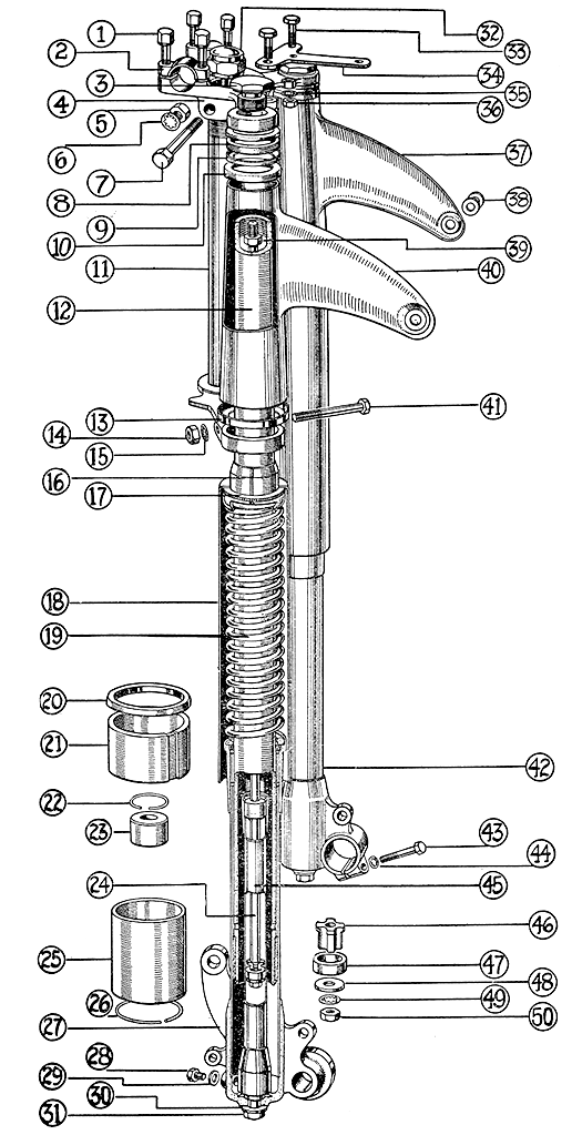
Key to Illustration of Fork.
|
Illust. No. |
Part No. |
Description. |
|
1 |
F269 |
Handlebar clip bolt |
|
2 |
F268 |
Handlebar clip |
|
3 |
F253 |
Fork damper piston rod adaptor |
|
4 |
F249 |
Top cross member |
|
5 |
SL56 /7 |
Clamping bolt nut |
|
6 |
LE369 |
Lockwasher |
|
7 |
SL110 /4 |
Top cross member clamping bolt |
|
8 |
F272 |
Rubber buffer for lamp bracket |
|
9 |
F278 |
Housing for buffer |
|
10 |
F271 |
Headlamp bracket assembly locating cup |
|
11 |
MAST |
Column and bottom cross member assembly |
|
12 |
F246 |
Front fork tube |
|
13 |
F257 |
Headlamp bracket assembly cup. Bottom |
|
14 |
SL56 /38 |
Bottom clamping bolt nut |
|
15 |
LE368 |
Bottom clamping bolt lockwasher |
|
16 |
F262 |
Fork tube split sleeve |
|
17 |
F282 |
Rubber washer for dust cover |
|
18 |
F245 |
Fork spring dust cover |
|
19 |
F252 |
Fork spring |
|
20 |
LE335 /2 |
Fork slider oil seal |
|
21 |
F256 |
Fork slider bush |
|
22 |
F267 |
Damper bush circlip |
|
23 |
F260 |
Damper bush |
|
24 |
F259 |
Damper piston rod |
|
25 |
LE216 |
Fork tube bush |
|
26 |
LE191 |
Circlip for fork tube bush |
|
27 |
MAS4 |
Slider tube assembly. Right hand |
|
28 |
SL8 /1 |
Drain plug |
|
29 |
A37 /5 |
Fibre washer for drain plug |
|
30 |
SL6 /50 |
Plain washer for damper tube nut |
|
31 |
SL56 /7 |
Nut. Damper tube to slider |
|
32 |
MAS6 |
Steering column lock nut |
|
33 |
SL109 /2 |
Bolt. Speedo bracket to cross member |
|
34 |
KA269 /3 |
Speedometer bracket |
|
35 |
LE368 |
Lockwasher |
|
36 |
SL56 /38 |
Nut for Speedo bracket bolt |
|
37 |
MAS8 |
Headlamp bracket assembly. Left hand |
|
38 |
F274 |
Headlamp bracket washer |
|
39 |
SL56 /38 |
Piston rod lock nut |
|
40 |
MAS9 |
Headlamp bracket assembly. Right hand- |
|
41 |
SL109 /6 |
Bottom cross member clamp bolt |
|
42 |
MAS3 |
Slider tube assembly. Left hand |
|
43 |
SL109 /3 |
Wheel spindle clamp bolt |
|
44 |
LE368 |
Lockwasher |
|
45 |
MASS |
Damper tube assembly |
|
46 |
F251 |
Damper valve |
|
47 |
F265 |
Damper piston |
|
48 |
F266 |
Damper piston rod washer |
|
49 |
LE366 |
Damper piston rod lockwasher |
|
50 |
SL56 /2 |
Damper piston rod lock nut |