Sparking Plug
The cylinder head is machined to take an 18 m.m. reach 14 m.m. diameter sparking plug. We recommend the K.L.G. type FE70. It is most important not to fit a plug of shorter reach.
Piston
A split skirt piston is fitted and if removed must be refitted so that the split is at the front.
Decarbonising and Grinding In Valves
Although basically similar to previous MAC engines, the modifications made when the aluminium alloy cylinder head and aluminium alloy jacketed cylinder were introduced make slightly different procedure necessary when dismantling the cylinder head.
The cylinder head now contains the overhead rockers, valve springs, and rocker bearings and the earlier pattern separate rocker box is deleted.
Removing The Cylinder Head
After removing the fuel tank and the usual items, disconnect and remove the oil feed pipe from the timing case to the rocker cover. Take out the eight cover bolts and remove the cover. Remove the sparking plug. Rotate the crankshaft with the kick starter until both valves are closed and the piston at top dead centre or thereabouts.
Take out three bolts securing the rocker bearing block to the cylinder head - the two end ones and the centre one - but leave the other two in place.
Remove the bearing block and the rockers, and lift out the two push rods, which should be marked " inlet " and " exhaust " respectively. They must be put back into their own places on refitting. The inlet is the nearer to the centre of the machine. Indelible pencil, if wetted, is a suitable marking medium. Take off the gasket from the rocker bearing block platform.
Take off the nuts and washers from the studs which hold the upper push rod flange to the head, and telescope the upper section of tube into the lower half, at the same time taking off the push rod guide plate and the two joint washers from the flange face. This guide plate is an important and vital part of the engine, and must be preserved for refitting.
Unscrew and take off the four cylinder head nuts—two accessible outside the rocker box on the left-hand side of the head—and the other two down inside the holes or openings in the bearing block platform.
Lift off the cylinder head, retaining the cylinder head gasket for use when reassembling.
Removing Valves And Springs
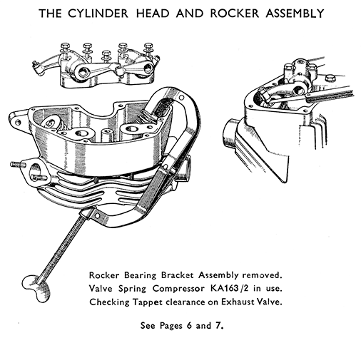
This is done in exactly the same manner as on the other models, but the Valve Spring Compressor Tool No. KA163/2 is required to clear the sides of the rocker chamber. The smaller size used on the previous types is unsuitable.
The valve top washers, cotters and springs are identical to the corresponding parts on earlier models, but there are loose bottom washers which fit over the valve guides and these come away when the springs are taken off.
Refitting The Cylinder Head, etc., After De-carbonising
Refit the cylinder head gasket, and the head. Fit and tighten down evenly the four cylinder head nuts. Be careful not to overtighten, as the tension on the studs increases as the engine heats up, and if the nuts are strained down there is a grave risk of damage occurring.
Place the push rod guide plate with a joint washer on each side of it over the push rod flange studs in the head, and push the upper flange up and over the studs. Fit and tighten the two nuts.
Check that the piston is at top dead centre of compression stroke and reset to this position if necessary, and thread the two push rods down through the pushrod guide plate and engage their ball ends in the cups formed in the cam followers.
The object of setting the crankshaft so that the piston is at top of compression stroke is to allow the rockers and bearing block to be fitted without the valve springs having to be compressed. If the crankshaft has been moved from the position in which it was set before removing the bearing block and has to be reset, the fingers may be rested on the tops of the push rods and their up and down movements observed as the crankshaft is rotated. By turning until the inlet (inner) push rod lifts and then drops and then turning the crankshaft very slowly whilst observing the piston through the sparking plug hole the correct setting is easily found.
Place the bearing block gasket in position, fit the bearing block, entering the tips of the rockers in the cups on the push rods, and refit and tighten the three bearing block bolts. Spin the push rods with the fingers to check that they are seated properly in the cups at the bottom.
Resetting The Tappet Clearances.
The cams are ground with pronounced quietening ramps and the positions at which the cams are set when checking or adjusting, the clearances is therefore rather critical.
When setting the inlet clearance set the crankshaft so that the exhaust valve is on the point of opening and turn it until the inlet valve is on the point of closing before setting the exhaust clearance.
The running clearances are .005-in. on both valves, to be checked and set when cold. Valve timing is checked with .020-in. clearance on both valves and the timing figures are as given on Page 54 for cam M.17.