F62-1R Service Manual
The front of the machine can be supported for wheel removal or alternatively the machine can be laid down carefully on the left hand side. If the second course is taken make sure that the petrol tank cap is secure and the dipstick firmly seated in the taper. Do not lay down the machine if a ' wet' battery is fitted. The Varley battery that is standard equipment is unspillable.
Slack off the brake adjuster fully, and slip the cable nipple out of the shackle or remove the split pin and clevis pin in order to detach it from the cam lever.
Remove the spindle nut from the brake end (right hand side) of the spindle, slacken the clamp bolt in the left hand side fork end. Support the wheel and drive the spindle out through the hub from the brake side to the left. A suitable punch is usually needed to follow up the spindle through the hub. When the spindle has been removed the wheel and brake assembly can be drawn out of the fork.
Push the wheel with brake assembly into place between the sliders of the fork engaging the slotted brake torque arm extension of the brake plate with the stop lug on the right hand side fork end. Line up the holes in the fork end with the hub and push in the spindle from left to right. As it emerges from the hub on the right line up the right side fork end to get the spindle to enter, and tap it through the rest of the way. Fit the spindle nut and tighten fully. Connect up the brake control cable. Set the machine upright standing on the wheels, and bounce the front end up and down sharply to ensure that the fork works freely. Finally tighten the spindle clamp bolt, and readjust the brake.
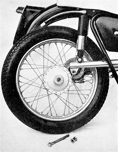
FIG. 9 REMOVAL OF REAR WHEEL.
The wheel is shown detached from the driving teeth.
The spindle and distance piece are on ground by tyre.
Support the machine on the centre stand. If several thousand miles have been covered and the brake has been readjusted a few times the surface of the drum in contact with the liners during braking may be worn a little larger than the mouth, and as the shoes will have been readjusted to allow for it, it may not permit the drum to come away. In such circumstances slack off the brake adjustment to "close" them before attempting to remove the wheel.
Unscrew the rear wheel spindle from the right hand side, and withdraw it from the hub and swinging fork. As it clears the hub remove the distance piece from inside the fork end. Keep the plain washer under the spindle head. Working from the left side of the machine, lean over the seat and pull the wheel off towards the right side. As it clears the brake shoes tilt the machine a little to the left and the wheel will come out under the tail of the mudguard (Fig. 9).
Check the condition of the driving splines in the hub and on the crown wheel shaft. If dry coat them sparingly with a little high melting point grease. Do not overdo the greasing and do not use ' soft grease or it will get into the brake and reduce the efficiency.
Standing to the left of the machine raise the wheel into position placing the brake drum over the shoes. Engage the driving splines by a semi-rotary back and forward movement of the wheel. When home hold the distance piece in place between the hub dust cover and the fork end and push the spindle into place. Tighten it up securely and readjust the brake.
Examine the spokes occasionally for lack of tension. Each spoke must carry a fair share of the load. Loose or broken ones involve the remainder being overloaded. Tighten any that are loose or replace at once any that are broken. When tensioning the spokes see that they are tightened equally.
If new spokes have to be fitted the tyre and rim band should be removed, otherwise the end of the new spoke may protrude from the nipple and chafe the rim band and eventually puncture the tube. File down any ends that stand proud of the nipples inside the rim.
| Front (Solo) | 16-lbs. per sq. in. | 1.12 kilos. per sq. cm. |
| Rear (Solo) | 22-lbs. per sq. in. | 1.54 kilos. per sq. cm. |
| Front (Pillion) | 16-lbs. per sq. in. | 1.12 kilos. per sq. cm. |
| Rear (Pillion) | 25-lbs. per sq. in. | 1.75 kilos. per sq. cm. |
The above pressures are the minimum and higher pressures will be required for extra loading. The pressure and load figures below will be a guide.
| Load per wheel in pounds | 200 | Pressure required per sq. in. | 16 |
| 240 | 18 | ||
| 280 | 20 | ||
| 350 | 24 | ||
| 400 | 28 | ||
| 440 | 32 |
Occasionally inspect the tyre treads for cuts, etc., and to remove any flints, or other sharp objects that have become embedded in the rubber. They can be prised out more easily if the tyre is deflated first.
Keep the tyres clean of all oil or grease. Wipe off immediately any that accidentally gets on them.