THE DYNAMO AND LIGHTING SET.
Lamps and Bulbs.
The headlamp is fitted with one Bifocal bulb and one parking (Pilot) bulb. The types used are :
| Headlamp Bulb : | 6-volt 30 x 24 watt. Double filament. Bifocal Pre-focussed type. |
| Pilot Bulb : | 6-volt. 3 watt. Single filament. M.E.S. Cap. |
To remove the lamp front to change a bulb or for other attention, free the clip below the lamp rim and pull the rim away from the lamp from the bottom first. Note that if it is proposed to do any work to the switch in¬volving any connections, always detach the cables from the positive terminal of the battery.
The bulbs are detachable from the back of the reflector after removing the bayonet-fixed contact assembly to which the leads are attached.
To replace lamp glass and reflector unit release the four—or more—fixing clips from under the lip of the head lamp rim. The unit will now come out of the rim.
Do not touch the highly polished inside optical surface of the reflector as this will leave finger marks which it will be most difficult to remove without damaging the surface permanently.
When replacing the reflector see that it is fitted correctly with the opening for the pilot bulb uppermost. Refit the lamp front at the top first—push it over the lower edge, engage the fixing clip.
On Viper and Venom models the rear lamp and stop lamp are combined in one body and the bulb used is a 6-volt 18 x 6W offset pin Stoplight bulb.
To reach the bulb take out two screws from the plastic " light " and remove.
The Dynamo. Maintenance.
The commutator and brushes should be inspected occasionally and should any blackening of the commutator segments be noticed the commutator should be thoroughly cleaned, and all brush dust blown out of the end casing. If the charge rate is satisfactory it is best to leave the dynamo and regulator alone and normally no major attention should be required within the first 10,000 miles running.
Before doing any work at all to the dynamo disconnect the leads from the positive terminal (+) of the battery.
The commutator and brushes are exposed by removing the commutator cover (Fig. 35) which is held to the end casting by a single central screw, after pulling out the single pin plug connecting the positive lead to the dynamo.
See that the brushes move freely in their holders. If stiff remove the brush concerned and clean the sides with a cloth moistened in petrol, or rub lightly with fine glasspaper. Always replace brushes in their original positions.
Brushes which have worn so that they do not bear firmly on the com-mutator, or which expose the embedded end of the flexible lead on the running face must be replaced at once.
The commutator must be clean, true, and free from al traces of oil or dirt. If dirty or blackened it can be cleaned by pressing a cloth against it and turning it round by the kickstart. If very dirty moisten the cloth in petrol, or hold against it a piece of fine glasspaper whilst turning.
Clean away all traces of dust or carbon before refitting the brushes.
Testing. (Fig. 34.)
The dynamo can be checked quickly and with very little trouble by removing the driving belt, and the commutator cover, and pressing the cut¬out points together. If the dynamo does not begin to run as a motor from the battery current there is a fault in it.
This is not a 100% check, as in some circumstances a dynamo with a faulty winding may 'motor', but by testing in this way a lot of time can be saved.
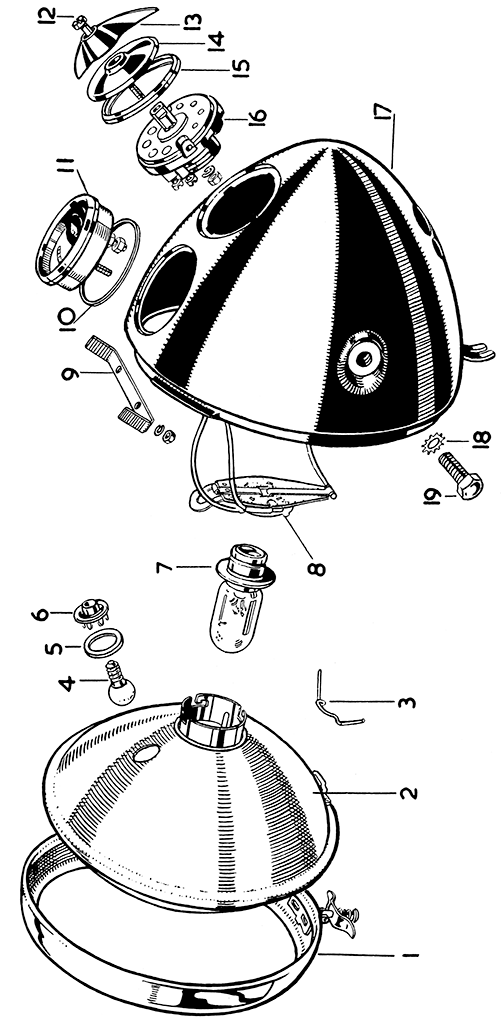 |
| FIG 32 MILLER HEADLAMP 179C.V. |
The work about to be described should not be undertaken unless the necessary equipment is available and is best entrusted to a Miller Service Agent.
Remove the commutator cover screw, then remove the cover, exposing the commutator and end bracket. Disconnect the three outside leads (Regulator and headlamp) from terminals D. B. and S. Clip the negative lead of a good quality moving coil voltmeter, reading from 0 to 10-volts to a clean earthing point on the dynamo, and clip the voltmeter positive lead to terminal B.
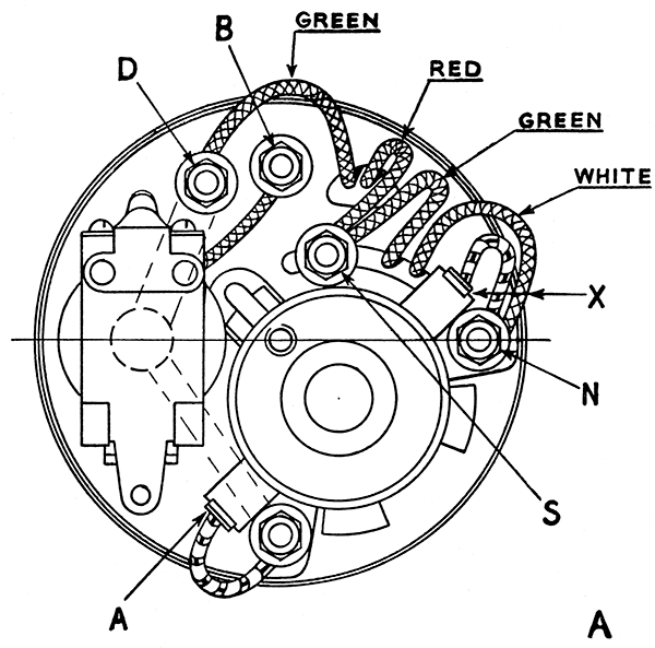 |
| FIG 34 DYNAMO LEADS |
Start the engine and slowly increase its speed. If no reading is shown on the Voltmeter transfer the positive lead of the voltmeter to terminal D. If a reading is now shown the cut out is at fault and should be adjusted (see page 83). If no reading the fault is in the dynamo.
On no account must the engine speed be increased to such an extent that a reading 8 volts is exceeded during these tests.
If dynamo and cut-out are in order, re-connect the three leads to ter-minals D. B. & S., and test voltage regulator. (See paragraph on Regulator page 80.)
Removal.
Electrical breakdown of the dynamo is most unusual, and the unit should be tested as described above before assuming that removal is necessary.
The removal of the dynamo is described on page 33.
Dismantling. (Figs. 34 and 35.)
Take off the armature shaft nut and washer, and draw the pulley off the tapered end of the armature shaft with a " Claw " extractor, being most careful when using the extractor not to break the thin flange of the pulley.
Remove brushes A and X (Fig. 34) from their holders. Unscrew and remove the two long through bolts (H37, Fig. 35) securing both end castings of the dynamo yoke. The countersunk heads of these screws can be seen at the driving end.
With a 3/8-in. diameter metal punch and hammer, tap the armature shaft at the commutator end. As soon as the ballrace at the commutator end is clear of the casting, the armature with the driving end casing can be withdrawn.
If it is necessary to remove the driving end casting from the armature shaft, first take out the pulley key (if fitted) from the shaft, and then unscrew and remove the bearing lockring (H38, Fig. 35) which is screwed on the armature shaft just behind the tapered portion.
Do not in any circumstances attempt the removal of the lockring by knocking it round with a punch. Always use a special pin spanner as shown (Fig. 37). This spanner is quite easily made from the details given in the illustration.
Support the bearing retaining plate firmly and press out the armature shaft. Take care not to damage the threads or bend the shaft when removing it.
To remove the commutator end casting from the yoke, first disconnect the four insulated leads at D, N & S (one each white and red, and two green) which pass through the end casting to the field coil (Fig. 34).
The end casing can then be pulled away from the yoke, drawing the four leads carefully through the accommodation slots in the casting and being very careful to avoid damaging them.
Commutator and Brushes.
Check the brushes for cleanliness, condition, and freedom in their holders. If either are stiff, free off as described previously. Inspect the commutator and if not badly worn clean up by polishing with fine glass-paper. To do this whilst the armature is out of the dynamo, it is advisable to rotate the armature in a lathe and hold the glasspaper against the revolving commutator in this way ensuring that it is true. If required, the commutator micas separating the segments must be undercut afterwards to a depth of approximately .025-in. They must not stand level with the rubbing surfaces of the segments. Clean up carefully afterwards when the armature is ready for refitting.
If new brushes are fitted they must be properly bedded to ensure that they make good contact with the commutator. To do this it is necessary to postpone the fitting until the armature is once more assembled into the dynamo.
To bed the brushes pass a thin strip of superfine glasspaper between the commutator and the brushes with the smooth side of the paper against the commutator. Press each brush in turn lightly on to the glass side of the paper and then pull the paper backwards and forwards several times. This will form the working ends of the brushes to suit the commutator.
Remove the glasspaper and clean out all glass and brush dust - preferably by means of a jet of compressed air.
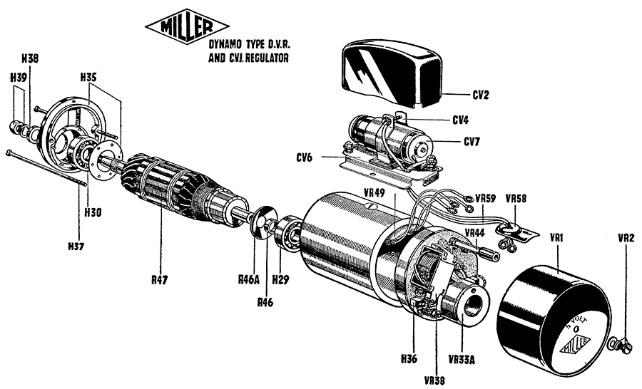 |
| FIG 35 DYNAMO EXPLODED VIEW |
Dynamo Bearings. (Replacement and Lubrication.)
It is very seldom that the bearings have to be replaced and they should not be removed unless absolutely necessary.
The drive end bearing is retained by a plate rivetted to the end casing (Fig. 35, H35). Only three of the projecting rivets are peened over and these must be filed off flush with the plate to remove it. On refitting the other three projections are used and are peened over to hold the retaining plate.
A small extractor will be needed to draw the commutator end ballrace off the shaft - it is not very tight.
On reassembly the bearings must be carefully packed with a high-melting point grease. Soft grease must not be used. Subsequent lubrication in service can be given by oiling sparingly through the commutator cover fixing screw hole, and to the drive end bearing through the grub screw hole in the top of the bearing housing.
Dynamo Armature. (Testing.)
The resistance of the armature coils measured between two adjacent commutator segments should be .2 ohms ± .01 ohms. Megger test to earth should not be less than 100,000 ohms.
Dynamo Field Coils. (Testing and Fitting.)
The resistance of the field winding (red and white leads) should be 4 ohms ± .25 ohm., and of the resistance winding (green leads) 7 ohms. ± .25 ohms. Megger test to earth and megger test between field and resistance windings should not be less than 100,000 ohms.
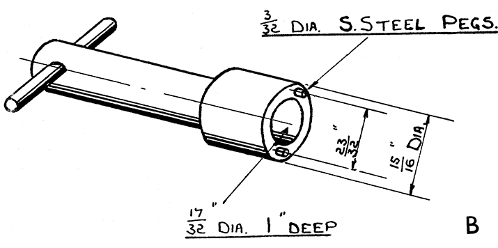 |
| FIG 36 |
When fitting a new field coil, force the yoke and pole on to a mandrel about 8-in. long, the diameter tapering from 1.773-in. to 1.767-in.
Grip the exposed end of the mandrel in a vice, and by using a robust screwdriver tighten the countersunk pole screw (Fig. 36) dead tight to hold the pole shoe firmly to the yoke.
It is most important that there shall be no air gap between the pole shoe and the inner face of the yoke.
Voltage Regulator.
As it is very seldom that the regulator gives trouble it is advisable, if it is suspected that it is at fault, to check the dynamo driving belt adjustment before doing anything else. For instance should it be found that the battery becomes discharged, although there is the normal charge reading of about 2 amperes only, it may be assumed incorrectly that the regulator is failing to increase the charge to compensate for the low state of the battery.
All these symptoms are however, also compatible with a slipping belt, which will drive sufficiently at low speeds to provide a 2 ampere charge but will not drive at higher speeds to provide the higher charge rate that the dynamo would give if driven properly.
The result is that the battery, although requiring a temporarily high charge rate to bring it back to a fully charged condition, does not receive it and gradually becomes discharged.
Normally the regulator provides complete automatic control of the charging so that the dynamo output varies according to the calls upon the battery or its state of charge. In the daytime with no lights in use, and with a battery in good condition the dynamo gives only a trickle charge, so that the ammeter readings will seldom exceed 1 or 2 amperes.
Should the lights be left switched on for only a few minutes, with the engine stationary, it will be found that on the engine being started and its speed increased the charge rate will be increased considerably until the battery is brought up to full charge again. Subsequently the charge rate will drop if there are no further calls on the battery.
The Voltage Regulator. (Testing.)
To test accurately special apparatus is necessary so that the work should be entrusted to a main Miller Service Agent who will have the necessary equipment.
If in normal running conditions, it is found that the battery is con-tinually in a low state of charge, and it is established that this is not due to belt slip, or to a defective battery, and if the dynamo has been tested and found satisfactory, and the cut-out in order, the regulator should be tested by substitution if a replacement is handy.
To test whether the regulator is at fault if no replacement is available, disconnect the battery positive ( +) lead, and connect a moving coil voltmeter to the two regulator base terminals (positive and negative), start the engine, and run it at a speed equivalent to about 20 m.p.h. road speed in top gear (approximately 1450 r.p.m.). If the regulator is in correct adjustment the voltmeter reading should be from 7.5 to 8.2 volts.
The Voltage Regulator. (Adjusting.)
If the voltmeter reading is below 7.5 volts, over regulation is taking place, causing the battery to be continually in a low state of charge. In the absence of a replacement, a purely temporary adjustment can be made by screwing out the negative (-) contact screw (which is visible at the conical end of the regulator cartridge), two complete turns.
Should the voltmeter indicate over 8.2 volts, which would cause over-charging, a temporary adjustment can be made by screwing out the positive contact screw at the other end not more than a quarter of a turn.
Note that these adjustments will not give the correct voltage readings, but will enable the machine to be run with improved results until a replacement regulator can be fitted. Note also that it is quite safe to run temporarily without the regulator cartridge in place. With the cartridge removed and the dynamo leads left in place, that is with the red collared lead connected to the base plate and the green collared lead to the clip bolt, the dynamo will give a reduced output with a maximum of about 3.5 amperes. It is advisable to fit a small block of wood or metal 1-in. long by 1¼-in. dia. into the clip temporarily, to allow the clip to be tightened and the lead held firm. Replacement as soon as possible is essential.
| MILLER CUT-OUT. (DVR TYPE DYNAMO). |
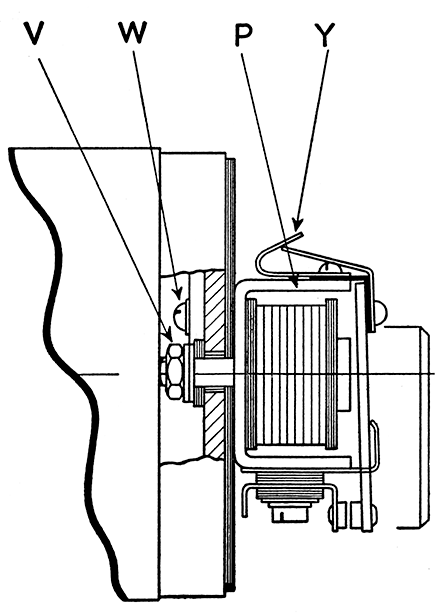 |
| FIG 37 |
| THEORETICAL DIAGRAM : MILLER DYNAMO (DVR) and REGULATOR |
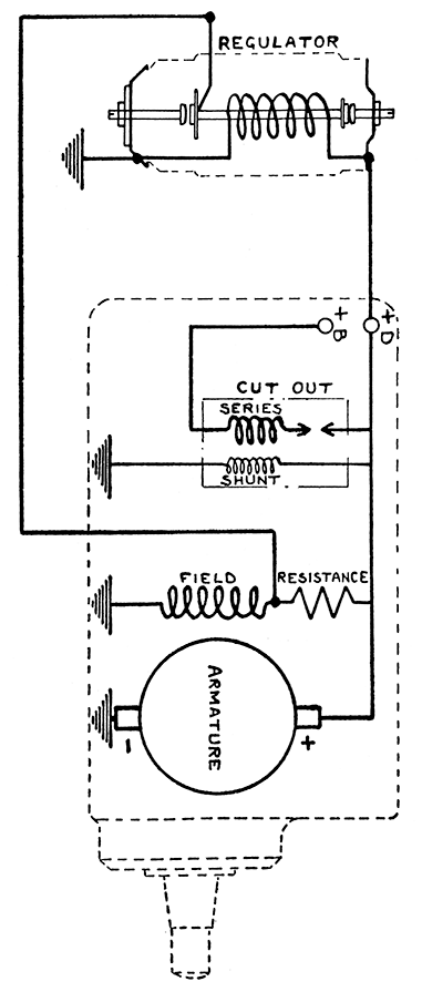 |
| FIG 39 |
The Cut-out (Type VR38). (Fig. 37.)
The cut-out (P) is attached to the dynamo commutator end casing by a nut (V) and is removable after taking off the commutator cover, the nut (V) and disconnecting the earth lead which is attached to the end cover by the screw and washer (W) and the lead to the centre one of the three terminals (B), Fig. 35.
The resistance of the series winding is .09 to .1 ohm. Resistance of shunt winding 55 to 56 ohms. The contact clearance is 1/32-in. (.031-in.).
The contacts should close at approximately 6 volts ,when a current of from 0. to ¼ ampere is being generated, and open when the current falls from 0 to ½ ampere discharge. The " off " and " on " tension can be adjusted by bending the brass tensioning bracket (Y).
The Ammeter. (Testing.)
With the engine stationary, switch on the lights. With the headlamp, main bulb, tail lamp bulb, and speedometer bulb the discharge will be 5.3 amperes. On switching off, the needle should swing back freely to zero. If at fault replace as soon as possible.
The Dynamo (Type DVR) Reassembling.
This is broadly a reversal of the process of dismantling already described but the following should be noted.
Attach the commutator end casting to the yoke first. Pass the red lead and the adjacent lead through the triangular slot and connect to terminals S and D respectively (Fig. 34). Pass the white lead and adjacent green lead through the long curved slot and connect to N and S respectively.
Fit the drive end ballrace to the end casting, refit the retaining plate and screws to the end casting. Place the assembly over the tapered' end of the armature shaft. Screw on the lockring tightly. With the commutator end bearing already on the shaft push the armature through the yoke, entering the ballrace in the commutator end casting and press gently home. Refit the two through bolts securing the ends to the yoke and tighten.
Replace the back half of the belt cover on the dynamo and fit the pulley washer, and nut, finally tightening the nut.
Fit the rubber bush protecting the leads into the commutator cover and connect up the leads : Red collared lead from voltage, regulator to " D," the plain lead from regulator to terminal " S " and the blue collared lead from ammeter (in headlamp) to " B."
Replace the brushes, fit the dynamo to the machine, afterwards fitting the commutator end cover.
A theoretical diagram of the Miller Dynamo and Regulator is shown in Fig. 39.

