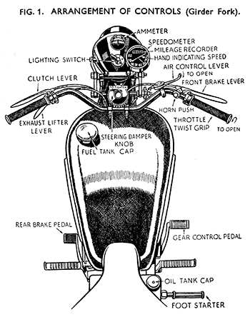
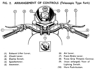
Hand Controls
Clutch Lever.
The larger of the two levers on the left side of the handlebar ; when pulled right back until it touches the grip disengages (or frees) the clutch, disconnecting the drive between the engine and the gearbox.
It must not be operated to ease the engine by slipping the clutch instead of changing to a lower gear, or be held up in order to "free wheel." Keep the hand off it when driving normally and do not hold it up with the machine stationary, and the engine running. If stopped in a traffic block select neutral position for the gears and release the lever.
The control cable attached to this lever should move freely for at least 3/16-in. before the pressure of the clutch springs is felt. This freedom will be likely to decrease with use, particularly on a new machine, or on one in which the clutch has been relined, particularly during the first few hundred miles' running.
Readjust as soon as this is noticed—as described on page 69.
Exhaust Valve Lifter.
The smaller of the two levers on the left side of the handlebar. When pulled towards the rubber grip holds the exhaust valve off its seating and relieves compression in the cylinder. Its use (as described fully later) is for starting up. In certain conditions it may be used when the machine is being ridden slowly with low gear engaged down exceptionally steep or difficult gradients in order to prevent the rear wheel locking on a loose surface. It is not used in normal driving on main or secondary roads.
The Air Control Lever.
A small lever clipped to the top of the handlebar on the right. Pull back towards the saddle to open the air valve. For details of use see pages 7 and 90
The Front Brake Lever.
Similar in appearance to the clutch lever, but fitted on the right-hand side. When pulled towards the grip applies the brake in the front hub.
CONTROL LEVERS.
These are all capable of being set on the handlebar in the best positions to suit any individual rider. A few moments spent in arranging their positions as desired are very well spent.
The levers are also adjustable for freedom of working. The Air lever should be adjusted so that whilst free enough to operate without difficulty it does not shut back of its own accord when machine is in use. The centre screw or hexagon head controls this setting. Turn clockwise to tighten.
The adjustment of the other levers is by tightening or loosening the fulcrum pin after slacking off the small fulcrum pin lock nut. Set the fulcrum pins so that freedom without slackness is obtained, otherwise levers tend to vibrate and wear the fulcrum pins excessively.
Oil all pivots and working parts from time to time.
The Horn Button.
Fitted to the left of the brake lever. Press to sound the horn.
The Throttle.
Operated by turning the right-hand grip. Movement back towards the rider opens the throttle valve in the carburetter and in most conditions increases the speed of the engine (and, when the gears and clutch are engaged) the speed of the machine. Keep closed when starting up. Movement of the twist grip when starting (familiarly known as " shaking the bottle ") will nearly always cause difficulty in starting.
Ignition Control.
Except on some early models there is no control for the ignition as on some other makes. The spark is advanced and retarded entirely automatically. On machines fitted with manual ignition control the lever is moved towards the rider to retard the spark.
Brake Pedal.
Slightly ahead of the left footrest. Press down to apply the rear brake.
† Gear Pedal.
Ahead of the right footrest. Press down to engage a higher gear. Raise to get a lower gear. After each movement the lever must be allowed to regain its central position. Keep the foot off the pedal when driving and do not kick or "stamp down' the pedal. See also "Driving Instructions."
† This control is arranged to work the reverse way to that described on all pre-war models and on some machines produced for the War Office.
Footstarter.
Behind right footrest. Footpiece swivels out of the way when not in use.
Fuel Taps
Situated underneath the fuel tank (one at each side) at the rear end. Must be shut off when the machine is left standing for more than a minute or so. The plungers work horizontally. To open the hexagon knob (marked PUSH-ON) is pushed towards the body of the tap (Fig. 3). To close, press the round milled knob (marked PUSH-OFF). Use only one tap and the other side will then act as a small reserve supply which is usually sufficient to run the machine about 3 to 4 miles. Either side may be used as the main supply. Always refuel as soon as possible after being forced to call upon the reserve and at once close the " reserve " tap again.
Lighting Switch
Fitted to the top of the head lamp behind the Ammeter. The lever-has four positions, indicated on the black moulding below the switch lever as follows :-
- OFF
- CH.--- The position for daylight running.
- H.--- Headlamp bulb and tail lamp on.
- L. --- Parking (dim) bulb on in headlamp and rear lamp on.
The dipper switch for the headlamp bulb is at the right of the clutch lever (see Fig. 2).
Instruments
Ammeter. In the top of headlamp. Indicates the flow of current into or out of the battery. Discharge (outflow) indicated on left of dial. Charge (inflow) indicated on the right.
Speedometer. On the top of the fork, registers total mileage run and indicates speed.


