Slack or incorrectly adjusted chains cause hard or snatchy running and excessive wear. The adjustment of both chains should be such that there is about ½-in. free up and down movement midway between the sprockets. Check the adjustment of the front chain through the inspection hole in the chain cover - never attempt to check with chains in motion - an elementary point which if forgotten may result in the loss of, or injury to, the fingers. Always check the adjustment in several places and allow the specified amount of freedom in the tightest place. The tension is nearly always found to vary slightly in different places as the sprockets are turned.
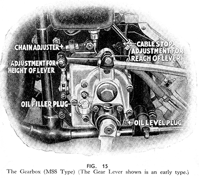
The primary chain is adjusted by moving the gearbox which is pivotally mounted and which in the case of the MOV and MAC models is mounted on a cross tube of the frame to which it is held by two halfclips. On the MSS model the gearbox is also pivotally mounted, but it is mounted on a bolt passing through the bottom of the housing, and the housing is held between the two rear engine plates. The driving load upon the rear chain always tends to pull back the gearbox and would tighten the front chain excessively if no positive means were provided to stop the gearbox " working " back. On the MOV and MAC models the top of the gearbox housing is provided with a shoulder through which passes a draw bolt secured to the left-hand rear engine plate, and on the MSS the draw bolt is fitted behind the rear of the two gearbox fixing bolts and passes through an " eye " bolt fixed to the engine plate (see Fig. 15). In each case two nuts are fitted on to the draw bolts by means of which it is possible to move the gearbox forward or backward on its mounting after the fixing clips, in the case of the models MOV and MAC are loosened.
Primary Chain Adjustment - MOV and MAC. (Fig. 36.)
Loosen the four nuts securing the half clips underneath, and loosen the rear nut on the draw bolt or gearbox adjuster. Screw this back about two turns. Now screw the front nut back in the same direction until it is tight and tighten up the nuts underneath to hold the half clips. Check the chain adjustment. Should the chain be too tight, loosen the nuts under¬neath again and turn the front nut forward a little and follow it up with the rear nut. Re-tighten the nuts underneath and re-check the chain. Finally check the adjuster nuts for tightness. Always make sure that the bolt which holds the adjuster or draw bolt to the rear engine plate is kept fully tightened up.
Primary Chain Adjustment - MSS. (Fig. 15.)
The adjusting nuts are on the right-hand side of the machine just along side the rear engine plate. To tighten the chain, screw the front nut forward along the draw bolt a little and then turn the rear nut forward until it is tight. Check the chain adjustment. If too tight, screw the rear adjuster nut slightly to the rear and follow it up with the front nut. Check the adjustment and finally check the adjuster nuts for tightness.
Rear Chain Adjustment - All Models.
If slackness in the front chain is taken up it will be necessary to re-adjust the rear chain to compensate for the amount that it will have been slackened by the rearward movement of the gearbox.
To re-adjust the rear chain slacken the nut on the dummy spindle at the left-hand side frame fork end and slightly unscrew the detachable spindle which passes through the fork end of the frame on the right-hand side. On early models of the MOV and MAC types it is also necessary to slacken the rear brake plate anchor bolt (Fig. 43). On machines fitted with the early type integral hub and brake drum (non-detachable), slacken the nuts on both sides.
The wheel can be pushed to the rear to take up excess slackness in the chain by turning the chain adjusting screws each a little at a time clockwise after loosening the lock nuts which keep them secured in the frame fork ends. The heads of the adjusters and lock nuts are situated in the angle made between the saddle stay tubes (from fork end lugs to below saddle) and the chain stays (between fork end lugs and lower part of frame) (see Fig. 42.) A convenient way to keep the rear wheel in correct alignment is to count the number of turns given to each screw and turn them an equal amount. Push the wheel forward so as to contact the dummy spindle and detachable spindle with the ends of the adjusters and hold it in this position when tightening the spindle and the nut on the opposite side.


