F62-1R Service Manual
Adjustment is made by means of a ' mid-way ' adjuster on the cable. This is situated about 10" from the handlebar lever. Readjustment is required when there is less (or more) than 3/32-in. free motion on the control cable. Excess play will prevent the clutch freeing, and the gears will grate on engagement. Insufficient play will cause slipping due to the clutch spring pressure on -the friction linings being decreased. Neglect of a slipping clutch will be liable to cause heavy wear and overheating of the clutch. Readjust immediately it is found to be required. (Fig. 2).
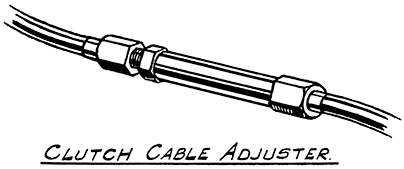
To decrease free movement slacken the adjuster lock-nut and screw the two parts of the adjuster further apart until the correct amount of freedom if left. Retighten the lock-nut as soon as readjustment is completed.
To increase free movement slacken the lock-nut and run it back a little way to allow the two halves of the adjuster to be screwed closer together. Retighten the lock-nut securely when the correct setting is obtained.
Remove the two generator cover fixing nuts and pull off the cover forward. There is a lip provided on it underneath to enable it to be prised foward if it sticks. Do not remove the cable support pressing that is fixed to the top of the stator plate.
The contact breaker points must be clean and free from grease and oil. Wipe clean if necessary with a petrol-soaked rag, but do not leave any lint adhering to them. They can be polished with emery cloth (Grade 0). If small ' pips ' have formed on them these must be removed by stoning or filing to leave a flat or slightly convex surface. See that the points close into correct alignment with each other. After trueing clean off all traces of abrasive.
When fully open the gap must be .015-in. This clearance is critical and incorrect setting will adversely affect the running of the engine.
To check turn the crankshaft until the contact points are fully open and try a .015-in. feeler gauge between them. It must just push through without play and without moving the rocker arm.
FIG. 3 GENERATOR WITH COVER REMOVED
showing front of stator plate assembly, ignition coils, timing unit and contact breaker
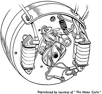
To adjust, slightly slacken the screw securing the slotted contact plate to the stator plate (Fig. 3). With a small screwdriver prise the plate carefully in the direction required to vary the adjustment. Check the setting and tighten the screw. Recheck in case the action of tightening the screw has altered the setting.
Support the front of the machine so that the front tyre clears the ground. The steering column must work freely from side to side without play. To take up play slacken the steering column lock-nut, accessible from behind and below the headlamp fairing. Apply the spanner to the hexagon adjusting nut below the fork cross member and turn clock-wise until the play is taken out, and the column begins to tighten in the bearings. Slack back the nut until full freedom is obtained and finally tighten up the lock-nut.
Adjustments, etc., are dealt with on page 71.
Remove the two rocker covers from the cylinder heads after taking out the two screws securing each cover. Remove one sparking plug and open the throttle control fully. Press the starter until compression is felt in the cylinder that has the sparking plug fitted. Remove the plug and by very gentle movement of the starter bring the pistons to the top of the stroke. On the opposite cylinder to that in which the piston is at the top of the compression stroke the two valves will be slightly open, which can be checked by observation of the working of the overhead rockers.
The clearance can now be checked on the side on which the piston is at top dead centre of compression stroke. With clearance gauges check the clearances between the rocker tips and the valve stems. When the engine is cold these must be .004-in. on the inlet rockers, and .006-in. on the exhausts.
To alter the clearance slacken the hexagon head lock-nut on the rocker spindle to be adjusted. With a screwdriver engaged in the slot in the head of the rocker spindle turn the spindle. When working facing the cylinder heads the clearances are decreased by turning the spindle on the operator's left hand side clockwise, and the one on the right anti-clockwise, i.e., when adjusting the clearances on the right hand side of the machine the exhaust rocker spindle must be turned anti-clockwise to reduce the clearance, and the inlet clockwise (Fig. 4), and vice versa when working on the left hand cylinder head.
Tighten the lock-nuts after the clearances have been set correctly being careful not to move the rocker spindles in the process. Recheck in case the spindles moved.
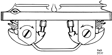
THE ROCKER CLEARANCE ADJUSTMENT
The Arrows indicate the direction of rotation to DECREASE
the clearances between the rockers and the valves.
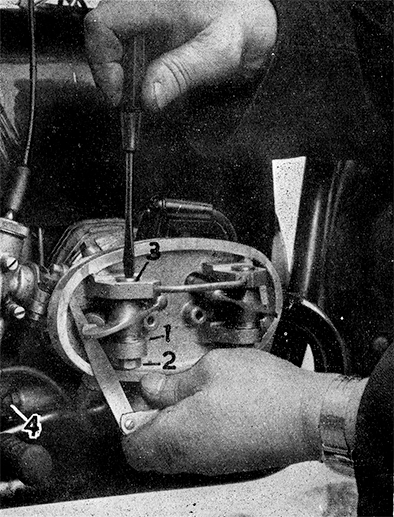
FIG. 5 ADJUSTMENT OF VALVE CLEARANCE
| 1. | Rocker thrust washer. | 3. | Head of rocker spindle. |
| 2. | Rocker spindle lock-nut. | 4. | Oil pressure adjusting screw. |
A feeler gauge is shown inserted between the rocker and end of valve stem.
The screwdriver is used to turn the spindle to alter the clearance.
Readjustment in ordinary normal service is not required as the pressure is set at the factory before delivery.
After an engine overhaul, or if the adjuster has been disturbed the pressure will require setting before the machine is put into service.
The take-off for the oil pressure gauge pipe is underneath the pressure valve body on the right hand side of the engine. There is a small hole (threaded ¼-in. B.S.F.) to which a threaded plug is fitted.
Remove the plug and attach a pipe, terminating in the standard Velocette banjo union LE330-3, by means of a hollow bolt LE329. A suitable pipe and gauge can be supplied by the Service Department.
See that the oil sump and filter chamber are filled with oil. Loosen the adjuster lock-nut, and screw the adjuster into the body until it is about flush with the face of the nut.
Start the engine and run it very slowly, being careful to stop it imme¬diately if the pressure shows any signs of overloading, the gauge. In such circumstances unscrew the adjuster and start the engine again. Run the engine until the oil is hot, and then unscrew the adjuster a little at a time to bring down the pressure to 30-lbs. per sq. in at a road speed of 30 m.p.h. in top gear.
Always reduce the pressure to the figure required, never adjust upwards.
Tighten the lock-nut when the adjustment has been made correctly.
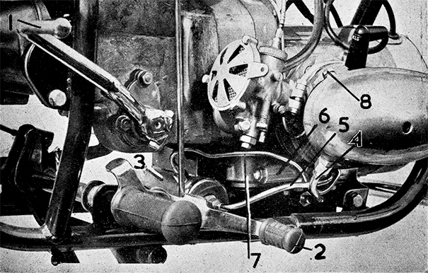
FIG. 6 RIGHT-HAND SIDE OF ENGINE (COVER REMOVED)
| 1. | Starter crank | 2. | Gear control pedal | 3. | Oil filter assembly | 4. | Cylinder head oil drain pipe |
| 5. | Oil feed pipe - pump to filter (Inlet) | 6. | Oil pressure relief valve body | ||||
| 7. |
Oil feed pipe - filter to bearings (Outlet) |
8. | Rocker oil feed pipe banjo union bolt |
Periodically check the gap between the electrodes and if necessary reset to .018-in. to .023-in. Never bend the centre electrode. See fuller instructions on page 72.
Readjustment must always be made before the linings wear enough to allow the lever or pedal to go over half their travel without applying the brakes fully. That is to say the full braking power must be obtained with no more than half the pedal or lever movement.
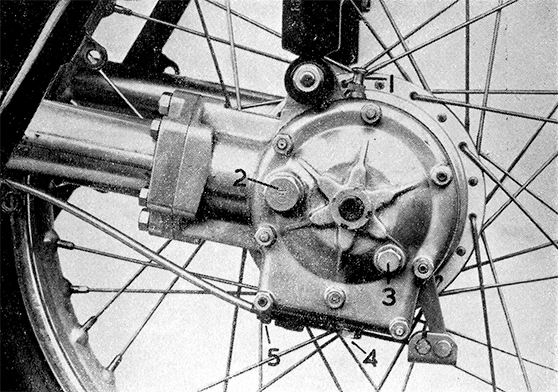 FIG. 8 REAR BEVEL DRIVE ASSEMBLY
| 1. | Bevel drive air vent | 2. | Bevel drive oil filler plug | ||
| 3. | Bevel drive oil level plug | 4. | Bevel drive oil drain plug | 5. | Rear brake cable adjuster |
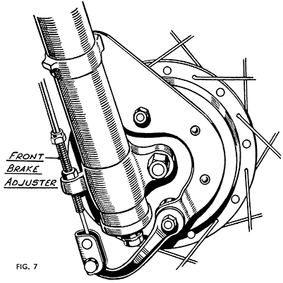
To take up the adjustment to compensate for wear screw the cable adjuster away from the cam lever after slackening the lock-nut securing it. The front and rear adjusters are shown in Figs. 7 and 8 respectively.
If the limit of the adjustment is reached and the brake linings are still in good order and still well above the rivet heads, relining can be postponed by fitting packing pieces between the brake shoes and the steel slippers. These are obtainable from the Service Department as Part No. LE479.


