F62-1R Service Manual
To take the clutch apart a Valve spring compresser KA163 /2 or a small hand press are essential, and it should be noted before stripping that the plates have to be accurately lined up after rebuilding otherwise the clutch bell will not engage the driving serrations and it will be impossible to refit the gearbox.
The clutch should not therefore be taken apart unless the Alignment tool LET 791 (Fig. 17) is available for reassembly.
To dismantle using the valve spring compressor fit the tool over the reduction gear shaft and clutch with the forked end resting on the pressure plate, and the tip of the screw in the centre depression in the bearing boss. Screw down until the plates are free from spring pressure, and take off all eight nuts and lock-washers from the clutch spring pillars. Release the compresser gradually and take the various components off.
When using a press rest the bearing boss firmly on the base of the press and bring the ram down on the pressure plate. Hold compressed whilst removing the clutch pillar nuts; then release slowly.
Removal of Clutch Driving Plate
(For access to starter pinion or reduction gear shaft oil seal).
Hold the reduction gear firmly to prevent rotation and unscrew the lock-ring after bending back the tab of the lock-washer. Tool LET780 is used (Fig. 13).
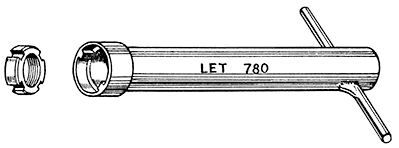
FIG. 13 Service Tool No. LET780 Lock Ring Tube Spanner
If the gear is fixed in a vice the jaws must be covered with soft metal clamps to avoid damage. Alternatively refit the clutch housing assembly to the crankcase, engaging the reduction gear pinion with the crankshaft pinion, and hold by preventing the crankshaft from turning.
The driving plate withdraws from the splines after the nut and tabwasher have been taken off.
Removal of Reduction Gear Shaft and Starter Pinion.
Pull the gear and shaft assembly out of the bearing in the clutch housing. If the oil seal is sound and there has been no leakage of oil into the clutch from the engine do not disturb it.
Renewal of Reduction Gear Shaft Oil Seal.
To fit a new oil seal the Service Tool LET786 with appropriate collar, will be essential (Fig. 14).
Press the old oil seal out through the bearing. Note which way it was fitted. Put a new oil seal on the special tool as shown and push the tool through the bearing. Fit the collar LET786 /7 and the nut. Screw down the nut until the seal is firmly in place.
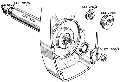
FIG. 14 Service Tool LET786 For fitting oil seals.
With extra Collars, LET 786/4, LET 786/5, LET 786/6 and LET 786/7.
Renewal of Starter Pawls and Pinion.
Remove the oil seal collar from the reduction gear shaft, and withdraw the bearing collar. The starter pinion is now free to come off.
Examine the pawls for wear. When new the width of the flats on the ends that engage the pinion is 1/32 -in. These will widen with use, and when worn wider to an extent that they do not engage the pinion properly must be renewed. If the pinion has to be renewed fit new pawls as a matter of course. They are rivetted to the gear and the old rivets must be punched out, and new ones fitted with the new pawls (Fig. 15).
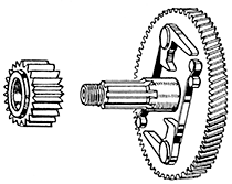
FIG. 15.
Showing the assembly of
starter springs and reduction
gear on current types of unit.
Oil the shaft, spread the pawls apart, fit the pinion and the bearing collar, the latter with the flanged side towards the pinion. Press it home and release the pawls.
Refitting the Reduction Gear Shaft Assembly.
Oil the bush and enter the shaft through it locating the bearing collar in the bearing. Oil the oil seal collar and fit it over the shaft pushing it into place through the oil seal. Replace the clutch driving plate on the splines, fit a new tab washer, and tap the tab into position in the plate. Screw up the lock-ring and when tight bend back a tab of the washer into one of the serrations in the lock-ring.
Examine the clutch friction linings for wear and if necessary obtain replacements. Verify that the clutch springs are of equal free length. If any have settled the whole set should be renewed. New springs should invariably be used if there has been clutch slip, and when new friction linings are fitted.
Fit the springs with their cups into the holes in the driving plate (Fig. 16). Assemble the pressure plate with the thrust button and oil thrower facing outwards as shown, and follow up with the friction linings and floating plates alternately. One of the floating plates is cranked' to give a progressive clutch take-up. It is immaterial whether this is fitted before or after the flat one.
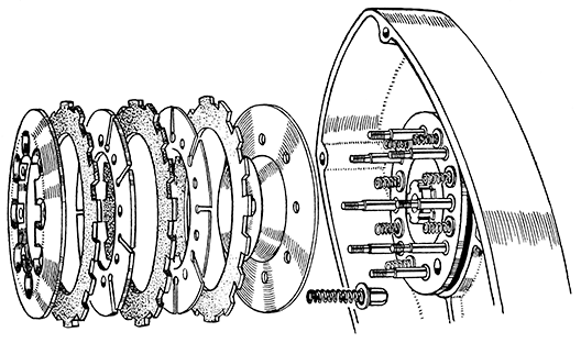
FIG. 16. Positions of the various members of the clutch assembly.
Using a press or a spring compressor (KA163 /2) depress the pressure plate to allow the fixed plate to be fitted over the studs. Fit the lock-washers and nuts. Release the pressure plate when all the nuts are tight.
Place the Alignment Tool LET 791 (Fig. 17) loosely over the clutch and once more depress the pressure plate to free the plates. Hold the springs compressed and line up the serrations on the friction plates to allow the tool to fit over them. Centralise the tool and plates by rotating the tool and locating the internal shoulder (or projections if a steel tool) over the edge of the fixed plate. Care in carrying out this part of the work is essential as imperfect alignment will prevent the gearbox being refitted.
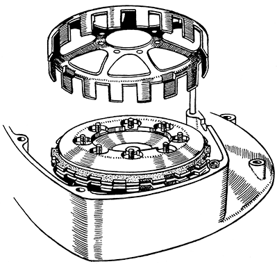
FIG. 17. Clutch alignment tool LET791 must be used to line up the clutch plates
and must be correctly located over the outer edge of the pressure plate.